• Hey Guest!
    British Car Forum has been supporting enthusiasts for over 25 years by providing a great place to share our love for British cars. You can support our efforts by upgrading your membership for less than the dues of most car clubs. There are some perks with a member upgrade!

    **Upgrade Now**
    (PS: Upgraded members don't see this banner, nor will you see the Google ads that appear on the site.)
Tips
Tips

TR2/3/3A TR3 Restrictor Valve

martx-5

Yoda
Country flag
Offline
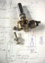
There's a restrictor valve on top of the five way brake union on the front right side of the frame. See item #43 on this Moss plate.

What is it there for, and can it be easily eliminated, as it doesn't appear that anyone carries the item.
 
It acts like a check valve to keep the pads close to the discs... in some cases too close as it can induce some drag.

If it is not wanted, rather than remove it one usually just remove the guts but retains the shell so everything still bolts up easily.

I gutted mine a few years back to relieve some brake drag I was getting but put the insides back in this year as I longed for the firmer pedal. Some of the drag may have been that it was a bit gunky in there, by removing and reinstalling I may have taken care of that. In any case the drag doesn't seem so much of a drag now.
 
I read stories of rear brakes locking up at speed due to gunked up restrictor valves. So, I removed the restrictor as the rear brakes were locked up when I first received the car anyway. I never reinstalled it since the brake system rebuild (more like replacement) but all seems to function OK with out it. I have gone through a few brake light sending switches though but not sure that those failures are caused by the removal of the restrictor. I'm also using Dot 5 and have a good solid pedal. This worked for me and may not provide the same results in your setup so proceed with caution.
 
I'll try taking it apart and cleaning things up and see how it goes. If it gives me any trouble, I'll gut it.

As far as the brake light switch goes, we have one guy in the club that went through several brake light switches using DOT 5. He finally rigged up a switch up by the pedal box like the TR4's. Maybe it's the DOT 5 fluid that messes up the switch. Don't know why, but you are the second person I've heard having trouble with switches using DOT 5.
 
Art,

Discussed the Dot 5 and switch problem possibility a while back. I never did come to a conclusion one way or the other about the dot 5 because I also just installed an electrical push button brake light switch through the hole in the master brake cylinder housing.
 
Those pressure switches are often troublesome but I don't know that this can really be attributed to DOT5 (which seems to get blamed for a lot of things I haven't had happen).

To help my switch last a bit longer I added a relay on that circuit, particularly helpful since I have added a 3rd brake light and thus would be sending more current through that switch.

I used an old metal can type relay since it is visible under the bonnet if you're nosy enough to peer down in there.

Brake%20Light%20Relay.JPG
 
There has been a lot of discussion of this issue, and I think that the general consensus is that the current crop of switches are pretty much junk. The most effective fix, other than going to the mechanical switch, seems to be the installation of the relay.
Jeff
 
Aloha,

I used to think DOT 5 five maybe contributing to the bi-annual brake light switch failure. I have dissected three of these over the past four or five year an have not seen any evidence of the DOT 5 leaking into the electrical side of the switch. The internal brass contacts and the copper or brass switch bar have always be pitted and burn to the point there is no continuity when pressure is applied.

A recent thread help me understand what is happening and in particular a post by David DuBois and a link to an article he had written about this problem.

"Be aware that replacement switches today are junk (I had one burn out in only two weeks) so you will need to make and install a relay/arc suppression circuit to make the switch last. See instructions for making the circuit at:

https://www.mgexperience.net/article/brake-light-relay.html"

The article he wrote contains easy to follow instructions on how to install the relay and arch suppression components.
I think I spent about $15 in parts from Radio Shack for everything. It might cost a little more if you use a metal covered relay like Geo has.
 
Phew! Now there's a man that wears both belt AND suspenders !

Art, I agree about gutting the residual pressure valve (which is what that thing really is). The main reason it's there is because the front spindles can flex under 'spirited' driving and cause a low pedal on the next brake application. And it works by causing the front brakes to drag slightly.

If spindle flex is a problem for you (most people never drive them that hard), there is a better solution available :
https://www.zeni.net/trf/TR6-250GC/119.php?s_wt=1152&s_ht=864

The RPV was not used on the first disc-braked TRs, and was deleted some time during the TR4 run, so it's obviously non-essential, IMO. I'd offer you the guts out of mine, but it's been so long I've no idea where they are anymore.
 
Harry_Ward said:
I read stories of rear brakes locking up at speed due to gunked up restrictor valves.
Cleaning up my inbox, and this statement caused a few random neurons to fire ... On a TR3A, the residual pressure valve is between the MC and all 4 wheels. So it would be impossible for it to only lock up the rear brakes.

If it did manage to hold higher pressure than it should, then it would keep all 4 brakes from releasing after they were applied, not just the rear brakes. But usually it just causes the front brakes to drag, because it doesn't hold enough pressure to overcome the return springs in the rear. (Which is still enough reason to disable it, IMO.)
 
All,
My restrictor valve (TR4) went south on me this weekend and all but locked the front brakes. I took the restrictor off and gutted it as I pulled it off. Master Mechanic here :smile: would like to find out how the two pieces fit back together. Here is my educated guess. Any feedback or idea are very welcome.
Thanks
Tim

myguts.jpg
 
The photo of mine also shows a sketch I made in 1987 when I restored my 1958 TR3A.

The lower piece in the colour photo in the preceeding is wrong way up. The TR2, TR3, TR4 Haynes Manual shows it like my sketch.
 

Attachments

  • 10201.jpg
    10201.jpg
    35.6 KB · Views: 448
Back
Top