• Hey Guest!
    British Car Forum has been supporting enthusiasts for over 25 years by providing a great place to share our love for British cars. You can support our efforts by upgrading your membership for less than the dues of most car clubs. There are some perks with a member upgrade!

    **Upgrade Now**
    (PS: Upgraded members don't see this banner, nor will you see the Google ads that appear on the site.)
Tips
Tips

TR2/3/3A TR3- New harness install, wiring questions.

hermanmaire

Jedi Hopeful
Offline
1960 TR3.

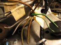
I finally got myself motivated to start tackling the new wiring harness. Everything looks good but I'm having trouble with the wiring diagram in my old triumph manual because there wires in the old harness that are not there in the new one.

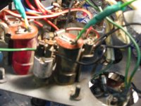
I'll start with the centre gauge cluster-
Theres a Ground on the metal frame of the centre cluster. There is no diagram of what is supposed to be grounded.

The way my old harness was wired, I had a ( black wire ) going from the wiper switch to the ground. Also had a ( black wire ) going from the fuel gauge to the ground.

There is nothing like this in the wiring diagram. Is this right?

Any help appreciated.
 

Attachments

  • 24770.jpg
    24770.jpg
    62.6 KB · Views: 1,028
Second question,

I am running a Delco Alternator with internal regulator- What do you guys do with all the wires that ran to the original voltage regulator if its no longer needed? Or is it?


Third question,

In the picture below, I have all these wires that run to the small fuse panel. In the wiring diagram they show no detail of what goes where. Any though?
Example- theres 4x green wires. which connects to which? or does it not matter since there on the same circuit.

Thanks
 

Attachments

  • 24771.jpg
    24771.jpg
    61 KB · Views: 1,014
DNK said:
Is this the wiring diagram you are using?
TR3 Wiring Diagram

Ummm... no. Thats actually quite a lot nicer. I am using the diagram in the haynes manual that labels the diagram for TR2, TR3, 3A.

I am going to have a detailed look at it right now.

Thanks for that.
 
Wait for Randall and Co. to pipe in. They're the 3 experts
 
hermanmaire said:
The way my old harness was wired, I had a ( black wire ) going from the wiper switch to the ground. Also had a ( black wire ) going from the fuel gauge to the ground.

There is nothing like this in the wiring diagram. Is this right?
Yes, that is correct (assuming the ground wire to the gauge was to it's mounting stud, not one of the terminals). The panel also forms the ground for the panel lights and the turn signal indicator.
 
hermanmaire said:
I am running a Delco Alternator with internal regulator- What do you guys do with all the wires that ran to the original voltage regulator if its no longer needed? Or is it?
Depends a bit on how you connect the alternator. The heavy brown/white (A) and brown/blue wires (A1) need to be connected together. I also tied the alternator in at this point, so I could keep the ammeter functional. (I'm funny that way, most of the instructions you'll find effectively abandon the ammeter function.) The black wire (E) needs to be grounded (it runs up to ground the dash panel, etc.) The small yellow wire (D) should go to the indicator terminal on the alternator. The larger yellow wire (also D, the one that doesn't run into the main harness) and yellow/green (F) can be removed and discarded. Or some instructions will use the yellow wire as a jumper from the harness yellow to the new alternator. (It's usually in pretty bad condition though, so I would suggest just making up a new wire to serve as the jumper. You could even make a subharness to run it together with the output and sense wires, if you choose.)

In the picture below, I have all these wires that run to the small fuse panel. In the wiring diagram they show no detail of what goes where. Any though?
Example- theres 4x green wires. which connects to which? or does it not matter since there on the same circuit.
It doesn't particularly matter, since they are all connected together through the terminals (and jumper) on the fuse block. The fuse block was just a convenient place for the factory to join the wires. But FWIW, the factory wiring shows the wire to the fuel gauge as being on terminal next to the fuse, and all the others connected to the terminal off to the side. Note that there is also a funny shaped flat jumper that has to go between those two terminals.
 
Last edited:
PS, Dan's diagram (the one linked to above) is probably clearer overall. But the factory diagram can be found in Practical Hints 6th ed, which you can download from https://docs.google.com/viewer?a=v&p...yNzUw&hl=en

It has some shortcomings (in particular it shows the RHD configuration), and doesn't show the gauges in quite the right positions, but it does have some information that I think is not on Dan's diagram (like which terminals the green wires connect to :smile: )
 
TR3driver said:
hermanmaire said:
The way my old harness was wired, I had a ( black wire ) going from the wiper switch to the ground. Also had a ( black wire ) going from the fuel gauge to the ground.

There is nothing like this in the wiring diagram. Is this right?
Yes, that is correct (assuming the ground wire to the gauge was to it's mounting stud, not one of the terminals). The panel also forms the ground for the panel lights and the turn signal indicator.

Hi Randal,

Thanks again for your help on another of my many problems. In the wiring diagram for the 3A and 3B the wiper switch has a Black wire that runs from the wiper motor to the switch, then from the switch to the dash ground.

I had a look at my original harness and the wiper circuit is like the TR2/TR3 with the Black/Green from the wiper motor then from the wiper switch a Green wire to the petrol gauge.

My new harness has the same colours as my original.

It does not really make any sense but I'll connect it up like it was and see what happens .
 
Randal,

is this alternator wired correctly? which generator wire would I connect to the white wire in the picture? If I understand your post above, the small yellow would
be going to the alternator. Is thats all that it takes to charge the battery?


in one of your posts you mention you modified your control box. do you have any details . Here is the post https://www.britishcarforum.com/bcforum/ubbthreads.php/topics/732839/1

Wiring is not my strong point.

Thanks again
 

Attachments

  • 24777.jpg
    24777.jpg
    56.6 KB · Views: 880
hermanmaire said:
...I had a look at my original harness and the wiper circuit is like the TR2/TR3 with the Black/Green from the wiper motor then from the wiper switch a Green wire to the petrol gauge... It does not really make any sense but I'll connect it up like it was and see what happens.

It is a bit counter-intuitive, but bascially the wiper motor is always offered power and is switched on & off by the ground.

I think that typically a wire with a black tracer is supplying a switched ground to a circuit.
 
hermanmaire said:
I had a look at my original harness and the wiper circuit is like the TR2/TR3 with the Black/Green from the wiper motor then from the wiper switch a Green wire to the petrol gauge.

My new harness has the same colours as my original.
The real difference is the wiper motor itself; early cars had a non-self-parking motor that got power through the switch. Later cars have a self-parking wiper motor that gets power directly from the fuse block (green wire), and the dash switch provides one path to ground. (The park switch inside the motor provides the other path.) The wire through the harness was the same black/green either way, so the harness difference is only the extra green wire to the wiper motor (or in some harnesses, it's actually two green wires that are joined together at the motor).

What puzzles me is that in your original post above, you said you had a black wire from the wiper switch to ground. Now you say it has a green wire to the petrol gauge (presumably the hot terminal rather than the gauge ground).

At any rate, I would suggest wiring to match your wiper motor. Otherwise you will find, as many have before you, that the fuse blows as soon as you turn on the switch.
 
hermanmaire said:
is this alternator wired correctly? which generator wire would I connect to the white wire in the picture? If I understand your post above, the small yellow would
be going to the alternator. Is thats all that it takes to charge the battery?
What you have is a good start, but you still need the main alternator output wire. This should be a heavy gauge wire (at least 10 AWG, I used 8, some folks go as big as 4). Simplest/easiest is to just run it from the big alternator terminal (the one that currently has the red wire on it) to the hot terminal on the starter solenoid (making a direct connection to the battery).

Your white wire should get connected to the small yellow wire in the harness, which goes to the "ignition" lamp on the dash.

in one of your posts you mention you modified your control box. do you have any details . Here is the post https://www.britishcarforum.com/bcforum/ubbthreads.php/topics/732839/1
That was someone else that modified their control box, not me. I might do it next time, though, haven't decided for sure yet. All that is really necessary, I believe, is to add a hefty jumper between the A and A1 terminals; and cut the connection to the D terminal. If you want to get fancy, you can also cut the connection to the F terminal and add a jumper from it to A and A1, to use as the sense line to the alternator. But since you already have the sense line wired (red wire on the alternator), it's probably not worth fooling with.
 
Last edited:
TR3driver said:
hermanmaire said:
I had a look at my original harness and the wiper circuit is like the TR2/TR3 with the Black/Green from the wiper motor then from the wiper switch a Green wire to the petrol gauge.

My new harness has the same colours as my original.
The real difference is the wiper motor itself; early cars had a non-self-parking motor that got power through the switch. Later cars have a self-parking wiper motor that gets power directly from the fuse block (green wire), and the dash switch provides one path to ground. (The park switch inside the motor provides the other path.) The wire through the harness was the same black/green either way, so the harness difference is only the extra green wire to the wiper motor (or in some harnesses, it's actually two green wires that are joined together at the motor).

What puzzles me is that in your original post above, you said you had a black wire from the wiper switch to ground. Now you say it has a green wire to the petrol gauge (presumably the hot terminal rather than the gauge ground).

At any rate, I would suggest wiring to match your wiper motor. Otherwise you will find, as many have before you, that the fuse blows as soon as you turn on the switch.


So I will I will leave the wiper circuit for last. As for the black wire, if you look in the first picture you will see the short black wire, that was connected to the wiper terminal and dash ground. But..... if you look at the petrol gauge, you will also see 2 green wires connected together. The shorter one was was also connected to the same wiper switch terminal with the black wire.

Also, I purchased a wiper motor from BCF board member but its a 3 wire unit. I will find out if that gives me any problem.

I think its safe to say, it very possible the car had electrical problem. Whats also not helping is that fact that I have never seen a complete/running TR3, I got this car pretty much in boxes. A lot of question marks but you and other board members are really, really helping me out.
 
So I am going to tackle all the areas that you cleared up for me, I hope to have power in the system by tonight.

I have another embarrassing question... the starter solenoid, again I have no good diagrams of what goes where.

I just wired up the alternator, does the wiring on the alternator look ok? Then I just connect the small yellow.

Also, is there a better ground location for the negative battery terminal? Or just use the same bulkhead/firewall location.
 

Attachments

  • 24785.jpg
    24785.jpg
    37.5 KB · Views: 805
  • 24786.jpg
    24786.jpg
    48 KB · Views: 784
hermanmaire said:
But..... if you look at the petrol gauge, you will also see 2 green wires connected together. The shorter one was was also connected to the same wiper switch terminal with the black wire.
Since that is clearly wrong (a direct short from power to ground), I'm going to guess that the DPO did that, trying to follow the TR2 diagram in the workshop manual.

<div class="ubbcode-block"><div class="ubbcode-header">Quote:]Also, I purchased a wiper motor from BCF board member but its a 3 wire unit. I will find out if that gives me any problem.
[/QUOTE]A photo would help. The original single-speed motor did have a 3rd terminal for ground; but if it really has 3 wires it may be a 2-speed unit.
 
My philosophy is "if it ain't broke, don't fix it"; so I've always used the ground on the bulkhead. Once, when I was having starter problems, I tried running the battery cable directly to a starter bolt, which made no detectable difference either with the shorted starter or with it's replacement.

But it's your car, so do what pleases you.
 

Attachments

  • 24788.jpg
    24788.jpg
    96.7 KB · Views: 917
Randal,

Thanks for those awesome labels on the picture. I will grab a picture of the wiper motor later.

I am going to head over into town to see if I can get the correct fuses for this thing. 25 and 35 amp.
I even had to look that up in the link you posted above to the TR3 manual.

The white wire for the coil, that connects to the positive right? Then I just connect the negative from the coil to the distributor body.

Thanks
 
hermanmaire said:
I am going to head over into town to see if I can get the correct fuses for this thing. 25 and 35 amp.

Ack! No, don't do that! The Lucas fuses are rated using a different system than modern fuses. If you are going to use commonly available glass fuses, you want 15 and 20 amp fuses.
 
Well, I worked late into the night yesterday, I finally connected the battery, about all that I had working was the gauge cluster light. That was until the gauge light for the tach shorted on the body. A few sparks and everything was dark again.

I think maybe the light switch got burnt. I am going to look into this today.

I will go get some weaker fuses like you suggest.

Thanks
 
Back
Top