-
 Hi Guest!
You can help ensure that British Car Forum (BCF) continues to provide a great place to engage in the British car hobby! If you find BCF a beneficial community, please consider supporting our efforts with a subscription.
There are some perks with a member upgrade!**Upgrade Now**
(PS: Subscribers don't see this gawd-aweful banner

Tips
- We have a special forum called "Member Articles" where you can submit actual articles for consideration for publication. Learn More
- Don't have an Avatar? If not, your avatar will default to the 1st character in your username. Go into "Account Details" to change your Avatar.
- Some basic forum navigation info: click
 Hey - did you know if you click on the title of a thread it will take you to the first unread post since you last visited that thread?
- Hey Guest - Is your British Car Club in our Clubs database? If not, send me a PM - Basil

- Looking for a local club? Click the "Clubs" tab above and browse hundreds of clubs world-wide.
- Add Android or iPhone APP: click
- Did you know - any picture or video you add in your posts in any marque-specific forum will also get added to the Media Gallery automatically.
- A few more tips about posting and replying: click
- Hey there Guest - be sure to keep your profile page up to date with interesting info about yourself: learn more
- More tips and tricks on Posting and Replying: click
 but were afraid to ask:
  STOP!! Never post your email address in open forums. Bots can "harvest" your email! If you must share your email use a Private Message or use the
  smilie in place of the real @
- Want to mention another member in a post & get their attention? WATCH THIS

- So, you created a "Group" here at BCF and would like to invite other members to join? Watch this!
- Hey Guest - A post a day keeps Basil from visiting you in the small hours and putting a bat up your nightdress!
- Hey Guest - do you know of an upcoming British car event?
 Pretty Please - add it to our Events forum(s) and add to the calendar! >> Here's How <<
- Hey Guest - you be stylin' Change the look and feel of the forum to fit your taste. Check it out
- If you run across an inappropriate post, for example a post that breaks our rules or looks like it might be spam, you can report the post to the moderators: Learn More
- If you would like to try some different "looks" or styles for the site, scroll to the very bottom, on the left and click the Style Selector.
You are using an out of date browser. It may not display this or other websites correctly.
You should upgrade or use an alternative browser.
You should upgrade or use an alternative browser.
TR2/3/3A TR3 heater install picture needed
- Thread starter mallard
- Start date


M
Member 10617
Guest
Guest
Offline
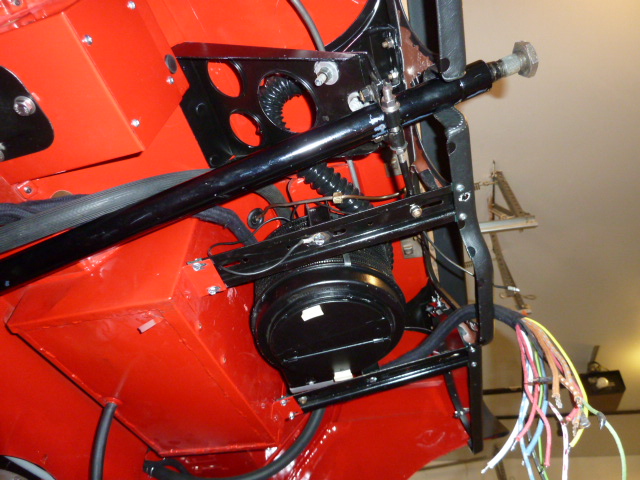
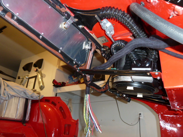
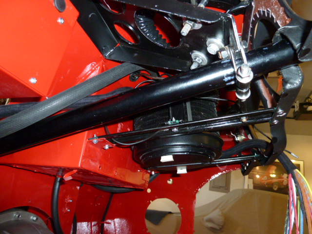
The only problem I have had with the heater assembly is that there is not much room above the heater for the heater inlet and outlet hoses to bend without crimping and stopping the flow of water. This apparently is a problem with the replacement hoses that are not easily bent. So check to make sure there is a reasonable curve to the hoses, or -- better still -- use pipe to firewall hose for the first few inches and then a connection to the standard replacement hose. The pipe to firewall hose is produced with a sharp bend. Just an idea.
luke44
Jedi Warrior
Offline
The only problem I have had with the heater assembly is that there is not much room above the heater for the heater inlet and outlet hoses to bend without crimping and stopping the flow of water. This apparently is a problem with the replacement hoses that are not easily bent.. ...
I got my hoses from TRF. They have small splines on them and were good for flexibility without kinking. They are not off the shelf from the local parts store. This may be one area you want to spend a few more $$.
I got my hoses from TRF. They have small splines on them and were good for flexibility without kinking. They are not off the shelf from the local parts store. ThiIs may be one area you want to spend a few more $$.
I have the heater installed but, my wiring diagram does not show where the two black wires are connected?
CJD
Yoda
Offline
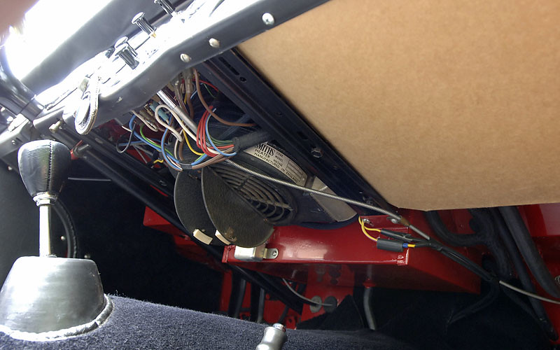
One should have a ring connector that is tightened under the lower right heater mounting bracket when you attach the bracket to the dash brace with a sheet metal screw. The bullet connector wire goes behind the tach and speedo to a bullet connector coming from the heater fan rheostat on the left side of the dash panel. The other wire to the rheostat crosses back to get power from the "live side of the windscreen wiper switch", which is ultimately off the "A2" fuse.
Thanks John,
Another wiring question for you. I have all my panel lights and rear lights working, I did hook up the rear harness. I can't get the four lights in the speedo and tach to work. I have them hooked up to the red/white connectors that runs the panel lights. I have the other speedo light blue/white hooked to the dipper button. No light? In addition, the engine turns over with the key on and you push the starter button, but, the ignition warning light, yellow wire going to D in the regulator and white to the ignition switch, doesn't come on?
Dick
CJD
Yoda
Offline
There should be a black wire with double round connectors that runs as a ground to the tach and speedo. It runs from one of the ground posts on the center instrument cluster and will then attach under one of the thumb screw nuts for each large instrument. Since the tach and speedo fit into the dash covered with vinyl or leather they may not get a good ground without the additional ground wire. I also don’t think that ground wire is included in the new harnesses...so you may have to dig through the old wires that came off to find it. Once installed all 5 lights should work, but the OEM style bulbs have lead contacts which do tend to need a “jiggle” every so often. The lead deforms slowly with road vibrations, so they tend to lose contact with the brass blade that powers them.
Let me get back to you on the ignition light...I need to look over the wiring diagram to refresh my memory...
Let me get back to you on the ignition light...I need to look over the wiring diagram to refresh my memory...
CJD
Yoda
Offline
Alright...
That light depends on a couple connections to operate.
First is a good connection to the start switch, so it goes negative when the switch is turned on (assuming you are still positive ground). So, double check with a test light that the white wire goes to battery positive with the ignition switch on.
Next is a good ground to the “E” post on the regulator, so test that E is positive at all times.
If those are good tests, then the most likely cause is the cutout is not “cut out”. Pull the cap on the control box and look for the 2 point contactors. One should be closed (the voltage regulating contact) and the other should be open (the cutout). Of course this is with the engine off, and the ignition both on or off. If the engine is running, then one contractor should stay closed at all times (cutout contact), and the other will cycle (regulator contact).
If you find the cutout contact closed, it may have welded shut, so pop it open and give it a good cleaning with a file and contact cleaner. If it is open and the ignition light is still not lit with the switch on and engine off...Then...
Ensure the yellow wire to the generator is intact and shows a connection to battery positive with some resistance (6-20 ohms approx).
If none of that works...make sure the bulb is good...or maybe check that first! Like I described above, these bulbs have a dab of lead at the tip that deforms and loses contact over time.