• The Roadster Factory Recovery Fund - Friends, as you may have heard, The Roadster Factory, a respected British Car Parts business in PA, suffered a total loss in a fire on Christmas Day. Read about it, discuss or ask questions >> HERE. The Triumph Register of America is sponsoring a fund raiser to help TRF get back on their feet. If you can help, vist >> their GoFundMe page.
  • Hey there Guest!
    If you enjoy BCF and find our forum a useful resource, if you appreciate not having ads pop up all over the place and you want to ensure we can stay online - Please consider supporting with an "optional" low-cost annual subscription.
    **Upgrade Now**
    (PS: Subscribers don't see this UGLY banner)
Tips
Tips

TR2/3/3A tr3 gas gauge calibration resisters

sp53

Yoda
Country flag
Offline
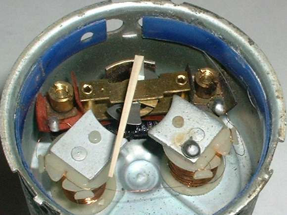
Hi all well I decided to try and fix the gas gauge on my tr3 using the MGA article with the calibration resisters. Things are not going to well. I am having trouble getting the needle to move in accordance with the article. I did get the needle to move some toward the full mark with one resister, but not much past 3/8 of tank. I am starting to think I have messed things up when I painted the gauge canister. It looks like one magnet needs grounding through the case, and perhaps I have insulated the ground from the case by painting it. I cleaned off the paint on the stud and bracket to provide a ground to case, but internally, I perhaps made an insulated surface. Nothing worse than screwing something up as I try to make it pretty.
Steve
 

TR3driver

Great Pumpkin - R.I.P
Offline
Don't forget that the resistor values shown in Barney's otherwise excellent article are not quite right for the TR3. I forget offhand if the TR is higher or lower, but it is different by 20-25% or so.

Have you checked the gauge resistance, using the case as one of the contacts? That would show you quickly if the problem is that the one coil is not grounded.
 

MGTF1250Dave

Jedi Knight
Silver
Country flag
Offline
Aloha Steve,

The MGA Tester is based on a sending unit with about 70 Ohms resistance. The typical TR3 sending unit is about 90 Ohms. I used a combination of 47 Ohm and 22 Ohm resisters to calibrate my fuel gauge. So two 47 in series (94 0hms) for full, a 47 and a 22 in series 69 Ohms for 3/4, a 47 ohm resistor for 1/2 and a 22 Ohm resister for 1/4. These resistors are commonly available at Radio Shack.

I had a similar problem as you describe when calibrating my gauge. Check that one or both the two coils that you need to move for adjustments have not become grounded to the instrument case. Those small fiberboard washer may crack, or the paint is creating a path to ground or in my case the wire from the coil touched the case. It seems to me that one of coil/electro-magnet is not working which is limiting the movement of the needle. Also, there are some raised dots on the bottom of the coil spools to keep the coil properly oriented as you slide it along the slot for adjustment. These can move out of the slot if the adjusting nut is loosened alot. If the metal plate on the top of the coil twists it can limit the movement of the needle.

Good luck.
 
OP
S

sp53

Yoda
Country flag
Offline
Well thanks Randall and Dave perhaps there is still hope. I see the little dots now and yes Dave one of them was off track. In addition, I will go up and get some different resisters. Anyways, I am getting continuity from the coils to case when I check it with an ohm meter. It looks to me like the little washers behind the little nuts are brass and touch the case? And the little thingie with the dots in the case is fiber? I noticed in the article the author says the F coil is case ground and the closer I look at the F post I see a copper washer touching case, and the E side might be fiber on the case. I just cannot see for sure because the washer looks rusted, but it must be fiber because it would most like be copper. I guess I will have to remove the washer to be sure. Either way both coil studs give continuity to case and that must be wrong unless the magnets do something I do not understand. I do have another gauge that does not work also so perhaps I can learn something there. Anyways I am all ears for help.
Steve
 

Geo Hahn

Yoda
Country flag
Offline
You can of course calibrate using the tank sender if all is in place. I use a length of stout copper wire bent into an L (with the upright very long and the foot short) and can use that thru the fill opening to either push the sender arm all the way down or hook it and lift it all the way up. Easier if the tank is not very full.
 

TR3driver

Great Pumpkin - R.I.P
Offline
sp53 said:
Either way both coil studs give continuity to case and that must be wrong
I believe that is not wrong, at least not necessarily. The coil that is grounded has one wire soldered to the metal core/stud; while the other coil does not. So there is no electrical problem if both studs are grounded. And I kind of suspect that the gauge won't work right if they aren't, since the magnetic field needs to flow through the studs and case. At least on mine, the washers over the slots were both metal (steel I think) rather than fiber. The fiber washers were on the electrical contact studs.

Of course, you do have to keep the wires from touching the case. And my biggest problem was having the coils twist until the armature rubbed on them. The little bumps seemed to be missing, so the only way I could get them straight was to remove the face and look.
 
OP
S

sp53

Yoda
Country flag
Offline
Back at it with the new resisters(47ohm) and I am having some effect or affect depending on how you look at. What happens is I have one resister on the T stud and the needle will swing to full, but only if I keep my finger on the T stud and kinda twist it some. It is like when I let go I lose the connection, perhaps ground. However, it is more like I lose power. The article suggest something like that could happen when he exclaims that the needle will move violently as the ground comes and goes. The problem is I can not keep it on the full side.
Steve
 
OP
S

sp53

Yoda
Country flag
Offline
Well I actually had it working (jubilation) just like the article illustrates. Hooked up the second resister and gauge went to half tank. Then hooked up the ground and gauge went to empty. The problem is if I touch the T stud just a little or bump the table I lose the connection and everything shifts to about 3/8 of tank. But after it shifts, and I hook up the second resister the 3/8 cuts in half to 3/16. I am thinking the little wire form the coil is touching case or the stud or something. I figured I needed to pop the face off but, I have not done that for a while. I grabbed an old gauge that did not work at all and pulled the face off that. I am not sure if I am doing it right because I kinda have to bend the needle up and wiggle off the face (is that right?). What I found in the broken gauge is the little wire( I presume that hooks the coils together) is broken. It just looks like they belong together. Does anyone know? Anyways perhaps I can reconnect that wire and fix that gauge. If anybody has any suggestions please comment.
Steve
 

TR3driver

Great Pumpkin - R.I.P
Offline
That's right, have to gently bend the needle and slide the face out from under it. Not something you want to do too often.

There is a bit of magnet wire that appears to run between the two coils (actually I believe it runs from the LH coil to the RH post, around the side of the RH coil) visible here:
fg_297.jpg


With it broken, I would expect the gauge to read way low.

If you try to mend it, note that the wire is coated with a thin layer of enamel that should be carefully scraped off with a small knife before trying to solder to the wire.
 
OP
S

sp53

Yoda
Country flag
Offline
Yes thanks you guys and that is the wirer that is broken. This gauge’s needle does not move at all. Thanks for the soldering tip Randall. Can you suggest some type of small soldering tool to go after such a small wire?
Steve
 
OP
S

sp53

Yoda
Country flag
Offline
Well I was able to solder the broken wire and got the old gauge working (elation). I unwrapped one turn from the coil and turned an eyelet in it with tweezers and did the same on the other end. I hooked the two together. Put a small screwdriver in behind the loops and bent a piece of solder up in a hook and stuck it in behind then just touched it lightly with a soldering gun, bingo. Now I still cannot get the other gauge working right. I think I created the problem when I painted the gauge canister. I took this gauge apart years ago because it was rusted. I glass beaded it and painted it silver. Perhaps there is aluminum in paint or something. I do not know what to think. I have been scratching the paint out of the way and those coils sit on nylon spools? I can get it to kinda work. Maybe I will have to take it apart again and take the paint off.
Steve
 

TR3driver

Great Pumpkin - R.I.P
Offline
Sorry I missed the question about the soldering iron, just now saw this. Sounds like you figured it out.

The only issue should be grounding one end of the one coil. No law says it has to be grounded through the post, you could add another ground wire if that is easier. I'd reread Barney's article, and spend some quality time with an ohmmeter before taking it apart again.
 
Similar threads
Thread starter Title Forum Replies Date
S TR2/3/3A tr3 gas gauge Triumph 5
S TR2/3/3A gas gauge TR3 Triumph 7
T TR2/3/3A TR3 Gas Tank Grounding Triumph 9
J TR2/3/3A TR3 gas tank mystery Triumph 5
T For Sale TR2 - TR3 Gas Cap for sale Triumph Classifieds 1
S TR2/3/3A TR3 gas filler cap Triumph 1
K For Sale TR3 Gas Cap Assembly Triumph Classifieds 0
S TR2/3/3A how to install a gas tank in an early tr3 Triumph 8
tinman58 TR2/3/3A TR3 gas tank? Triumph 2
T TR2/3/3A TR3 aluminum gas tank on eBay Triumph 4
T TR2/3/3A remove a tr3 gas tank Triumph 7
K TR2/3/3A TR3 gas tank inlet size? Triumph 2
M TR2/3/3A TR3 gas cap question Triumph 4
R TR2/3/3A TR3 gas tank Triumph 13
J TR2/3/3A Help!! Gas smell from Tr3! Triumph 21
S TR2/3/3A Tr3 Gas pedal height from floor Triumph 15
T TR2/3/3A TR3 gas tank vent Triumph 12
af3683 TR2/3/3A TR3 Trunk Plugs Near Gas Tank Triumph 3
af3683 TR2/3/3A Installing TR3 Millboard Gas Tank Cover Panel Triumph 5
T TR2/3/3A TR3 gas tanks Triumph 9
mountainman TR2/3/3A Tr3 Gas Additives Triumph 23
K TR2/3/3A 57 TR3 gas tank hold down strap mistery? Triumph 5
S TR2/3/3A One more tr3 gas tank? Triumph 1
S TR2/3/3A late tr3 gas cap? Triumph 5
S TR4/4A late tr3 and tr4 gas caps Triumph 4
S TR2/3/3A Tr3 gas cap vent Triumph 0
S TR2/3/3A tr3 gas tank vent Triumph 3
K TR2/3/3A TR3...Gas cap rubber gasket/seal in cap lid? Triumph 1
S TR2/3/3A gas tank in a 1961 tr3 Triumph 12
S TR2/3/3A Tr3 gas tank again Triumph 3
S TR2/3/3A Tr3 gas tanks Triumph 7
Tinkerman TR2/3/3A TR3 Gas Stop Tap Needed ! Triumph 6
K TR2/3/3A TR3 Gas Line Shut-off Valve Triumph 12
tinman58 TR2/3/3A Another TR3 gas tank ? Triumph 3
mountainman TR2/3/3A TR3 Gas Tank Question Triumph 7
H TR2/3/3A TR3- installing gas tank = nightmare Triumph 18
J TR2/3/3A gas leak on a TR3 Triumph 4
martx-5 TR2/3/3A TR3 Gas Tank Installation Triumph 5
RedTR3 TR2/3/3A TR3 - Gas odor and poor mileage Triumph 5
S TR2/3/3A Tr3 gas pedal Triumph 3
S TR2/3/3A Tr3 gas tank repair Triumph 9
J TR2/3/3A tr3 and unleaded gas Triumph 9
martx-5 TR2/3/3A TR3 Gas Tank Triumph 3
S TR2/3/3A TR3 Gas Mileage Triumph 9
D TR2/3/3A TR3 gas gage Triumph 2
S TR2/3/3A Tr3 gas pedal shaft socket Triumph 7
mctriumph For Sale front apron 57 Tr3 Triumph Classifieds 0
Rick_Thompson TR2/3/3A TR3 rack and pinion kit problem... Triumph 17
S TR2/3/3A differential hubs early tr3 and tr2 Triumph 22
S TR2/3/3A Tr2 and early tr3 differential. Triumph 10

Similar threads

Top