• Hey Guest!
    British Car Forum has been supporting enthusiasts for over 25 years by providing a great place to share our love for British cars. You can support our efforts by upgrading your membership for less than the dues of most car clubs. There are some perks with a member upgrade!

    **Upgrade Now**
    (PS: Upgraded members don't see this banner, nor will you see the Google ads that appear on the site.)
  • When posting a classified ad, you MUST select a prefix from the drop-down next to the subject line. If you don't you will get an error and your ad will not be posted!
Tips
Tips

TR2/3/3A Tr3 coil spring compressor

ekamm

Jedi Warrior
Offline
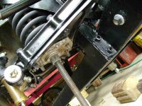
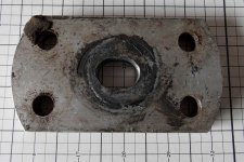
I am beginning a front suspension rebuild on my tr3a. I have found a number of archived threads and am confident in my ability to do this. My question of everyone is about a spring compressor of my own making. I am unclear as to which end goes where. Am I correct in thinking that I will remove the coil with the packing piece and the spring pan as a unit? Also, one end of the compressor is a large washer and nut and possibly a pin. the other end is either a rectangular plate or something sturdy that is round (i.e. Randall's half pulley)and a nut or two. Which end goes under the spring pan?
 
Yes- you remove all as one unit. I use a washer/double nut at the top, it basically takes the place of the upper shock mount. Then you need something suitable, like Randall's half pulley, to give you adequate support under the spring plate. I found a stout piece of steel with a hole in it that fit between the studs underneath the spring plate.
 
I got a compressor off ebay for a very good price -it was possibly a TRF unit that came with 2 lower plates with 4 holes each (one for the TR6 the other for TR3). Here's a pic of me putting mine back together. When I took it apart, the engine was removed before the shock, which complicates it a little. Aside from the possibility of dropping the car, it seemed pretty worry free. Make sure you've got plenty of clearance under the car before you start.
 

Attachments

  • 23789.jpg
    23789.jpg
    66.6 KB · Views: 501
The washer at the top is basically just to keep the nut from damaging the tower, it's not needed for strength. Mine is just an ordinary 3/4" flat washer (since I used 3/4" threaded rod; most folks use 5/8').

Here's a shot as I was taking TS13571L apart.

DSCF0031.jpg


Note that you don't have to have the trunnion washer and upper A-arm off, or the tie rod disconnected. I had taken them off to assess what parts to replace.
 
Thanks I'm using 5/8" rod as well. Texasknucklehead can you give me dimensions of the plate and spacing of the holes on the as well as the length of the rod? I plan on using the method spelled out in the shop manual unless the is a better way.
 
Just a tip, a little lubrication on the rod helps a lot. Also where the nuts turn against washer.
 
That link is pretty close to what I have, except mine is 1/2" thick, the ends are rounded, 4) 3/8" holes drilled and mine is a little narrower (2 1/2"). The threaded rod is 20" long.
 

Attachments

  • 23794.jpg
    23794.jpg
    65.5 KB · Views: 467
The diagram appears to be for a tr6 and I need it for the tr3
 
I don't believe it's actually important to drill it to fit over those studs; I only drilled mine because that was the piece I had and it was easier to drill than to cut it to fit between the studs. However, the pattern I used appears to be 1.375" by 3.125" on center.

Or you could always measure the studs on your car
grin.gif
(which is how I made mine).
 
ekamm said:
The diagram appears to be for a tr6 and I need it for the tr3

Sorry I meant to point that out and it looks like from Randall's measurements they are different.


Lets see, it's for a 6, you have a 3. Divide the dimensions by 2, you should be ok. :devilgrin:
 
I think that I will measure between and make a heavy rectangular piece to fit.
 
Sorry, I didn't pay close enough attention. The TR6 plate is about 3"x4 1/8" with 4 holes centered 3" and 1 5/8". The TR3 plate is 2 1/2"x4 1/2" with 4 hole centers at 3" and 1 3/8". The 4 1/2" is the longest it can be, and is rounded so the straight sides are less than 4" so it will fit into the pan. Mine is a very thick plate (1/2") -you don't want the rod to pull through.
 
Yup, TRF uses a 1/2" thick aluminum plate that fits over the studs. Others use ~3/16" steel that fits between the studs.
 
Thanks for the info I'll get it together this weekend and start the rebuild next week.
 
Howdy Folks,

I`ll be doing the same in the "Very Near Future" with my Engine & Trans Installed. Right now with Engine & Trans out; I have the "Shocks" un-bolted at the top. How do I get those suckers out thru the bottom? I see "4 Nuts" that appear to have to be removed but won`t that let the "Spring" go "Wherever it wants"?

Thanx for the Help,

Russ
 
Russ the spring pan which is attached to the lower wishbone arms holds the spring. Attached to that are the bolts that allow you to pull the shock out the bottom hole of the spring pan. The entire spring pan then comes off the lower wishbone arms and lowers with the compressor plate under.
 
Howdy Richard,

"Thanx" for the info. So; There are only "2" bolts that actually hold the "Shock" in place; Correct? If yes; Then I should be able to remove those "2 Bolts" and simply pull the "Shock" out without any concern for the "Spring" to shooting off in Outer Space or in my Face; Correct?

I know these are probably easy questions but I just wanted to 100% correct before attacking this.

Thanx Again,

Russ
 
On my 4A there were four bolts that hold 2 #'s 130 in this illustration. Those 4 bolts are what the compressor plate straddles once the shock is out.

4A Moss Front Suspension

Looking in Moss the 3 looks similiar but I see another piece under the spring plate so I will let someone else speak to the 3.

When removing the nuts there is no pressure like there is when the spring pan comes off. The shock simply drops out with the #130 brackets attached by one bolt #131 in the 4A diagram.
 
It works the same on the TR3, although "simply drops out" is not the phrase I would use! That extra piece is the rebound stop for the suspension, which comes off the 4 studs along with the brackets for the shock. The only other difference is that you start by removing the other rebound stop bracket from the frame.

And as noted the spring remains trapped by the spring pan; the shock & 4 studs have nothing to do with retaining the spring. Which is a Good Thing, since the shock has to come out before you can install the spring compressor.

I actually really like this design, since the spring is totally trapped by the compressor shaft and it's original seats, until after the spring tension has been released. Much safer IMO than the ones where the spring compressor grabs the spring directly and you have to remove the spring while it is still compressed. Many years ago I helped a buddy do his American car, where the spring had to be removed while it was compressed. When I picked the compressed spring up to reinstall it, the compressor slipped off and literally shot out into the street! Fortunately I only got my knuckles rapped, but it could have been much worse.
 
Back
Top