 but were afraid to ask:
 I put the body back on the chassis and have a few question about the spacers. How accurate is the book with there recommendations for the spacers? I saved all the original spacers and it is nothing like what the book says. No way can I use 4 square spacers per pad. It looks like mine had 3 in the front and 2 in the back. And the spacers with the aluminum washers no way to use the thick and thin pad in the front, and two thin on the back. Should work fine if I reverse it.

-
 Hey Guest!
British Car Forum has been supporting enthusiasts for over 25 years by providing a great place to share our love for British cars. You can support our efforts by upgrading your membership for less than the dues of most car clubs. There are some perks with a member upgrade!**Upgrade Now**
(PS: Upgraded members don't see this banner, nor will you see the Google ads that appear on the site.)

Tips
- We have a special forum called "Member Articles" where you can submit actual articles for consideration for publication. Learn More
- Don't have an Avatar? If not, your avatar will default to the 1st character in your username. Go into "Account Details" to change your Avatar.
- Some basic forum navigation info: click
 Hey - did you know if you click on the title of a thread it will take you to the first unread post since you last visited that thread?
- Hey Guest - Is your British Car Club in our Clubs database? If not, send me a PM - Basil

- Looking for a local club? Click the "Clubs" tab above and browse hundreds of clubs world-wide.
- Add Android or iPhone APP: click
- Did you know - any picture or video you add in your posts in any marque-specific forum will also get added to the Media Gallery automatically.
- A few more tips about posting and replying: click
- Hey there Guest - be sure to keep your profile page up to date with interesting info about yourself: learn more
- More tips and tricks on Posting and Replying: click
 STOP!! Never post your email address in open forums. Bots can "harvest" your email! If you must share your email use a Private Message or use the
  smilie in place of the real @
- Want to mention another member in a post & get their attention? WATCH THIS

- So, you created a "Group" here at BCF and would like to invite other members to join? Watch this!
- Hey Guest - A post a day keeps Basil from visiting you in the small hours and putting a bat up your nightdress!
- Hey Guest - do you know of an upcoming British car event?
 Pretty Please - add it to our Events forum(s) and add to the calendar! >> Here's How <<
- Hey Guest - you be stylin' Change the look and feel of the forum to fit your taste. Check it out
- If you run across an inappropriate post, for example a post that breaks our rules or looks like it might be spam, you can report the post to the moderators: Learn More
- If you would like to try some different "looks" or styles for the site, scroll to the very bottom, on the left and click the Style Selector.
You are using an out of date browser. It may not display this or other websites correctly.
You should upgrade or use an alternative browser.
You should upgrade or use an alternative browser.
TR2/3/3A TR3 body back on chassis for trial fit
- Thread starter mallard
- Start date
 Btw... What color is that?
angelfj1
Yoda
Offline
mallard said:Has any body installed some rubber between the floor and the outer frame rail? The book shows none, but mine is very tight. I think it would help.
Keith: I assume that you have this diagram. It's from the parts catalog.
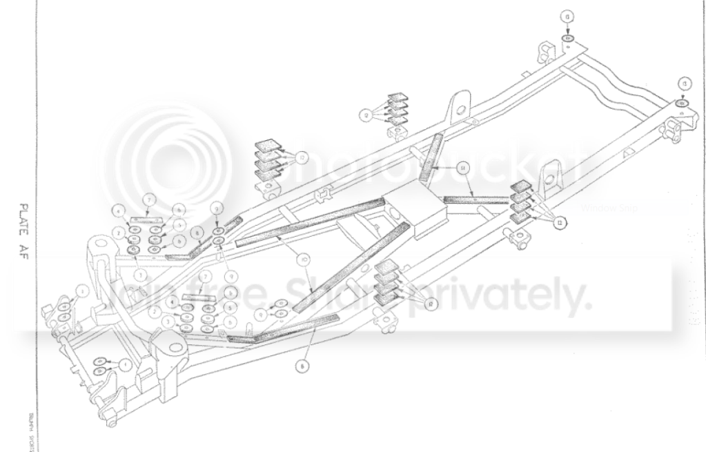
I wanted to be sure that you were aware that there were rubber strips in several areas in addition to the thick and thin pads and aluminum spacer things. Over the years I have been involved with dismantling quite a few TR's and the number of spacers, pads, etc. has never been the same. This makes sense. The pads shown are for illustration only and to provide a starting point. These cars had lots of variations and these spacers were a way to make up for the variation in fit between the body shell and chassis. It will take some fiddling to get it right. Even when you think everything is perfect and you start to tighten the bolts, the pads will compress and you will see things like doors binding and changes in the gaps at the "A" and "B" post area. Don't get stressed if that happens. Just let things settle over night and then you may have to add or subtract a pad or two.
Something that might not be obvious, is to have the car set up on the wheels and tires with correct tire pressure and on a level garage floor. We used an inexpensive laser level set up on a tripod and panned along the rockers (for example)to get some reference points. Remember when people used loose-leaf paper? Remember those little donuts that were used to repair the torn out paper holes. Well, they make excellent laser targets! We numbered and stuck them on at strategic places and then recorded the height from the floor and the distance from an arbitrary "construction line" we drew on the garage floor. We started with the off side and then repeated this process on the near side. Then we repeated this on the front and back of the car. After a while it becomes obvious when a point is higher or lower than desirable. BTW, there is a section of the parts catalog with reference dimensions. We checked most of those and were surprised how close we got.
Our biggest challenge was the garage floor which was not so level - so we did need to do a bit of fudging!
Good luck!
Laser level I never thought of that, thanks. I know it's going to be a lot of trial and error, that's why I'm doing it this way before paint. I think I will get all the mounting bolts started then start hanging the panels from back to the front, and then tighten everything down and see what starts to shift.
The engine and trans will have to be installed to get even furture needed adjustments as the frame settles with the weigth on the tires. This is where the head banging starts to come into play, work and rework and try again.
The area I wanted to place the rubber between the outer rails and the floor is in between the the square mounting pads.
The color is only primer, will be painted Winchester blue in the end.
DrEntropy
Great Pumpkin
Offline
:lol:
An anecdotal tale:
When I first tore down the Elan to repair some frame damage, to be dead-sure the thing was level we drilled into the concrete floor, planted threaded anchors into it at various points and used 5/8" all-thread and steel (3/8" IIRC) plates to true up a "platform" to hold the frame. Plumb bob and "chalk lines" on the floor for checking geometry. It may not work as well for panel fitting, as the chassis flex once the car is on its feet may shift alignment. But a thing to keep in mind for chassis checking/tweaking on an irregular floor.