• Hey Guest!
    British Car Forum has been supporting enthusiasts for over 25 years by providing a great place to share our love for British cars. You can support our efforts by upgrading your membership for less than the dues of most car clubs. There are some perks with a member upgrade!

    **Upgrade Now**
    (PS: Upgraded members don't see this banner, nor will you see the Google ads that appear on the site.)
  • When posting a classified ad, you MUST select a prefix from the drop-down next to the subject line. If you don't you will get an error and your ad will not be posted!
Tips
Tips

TR2/3/3A TR3 Battery Box Installed

mallard

Luke Skywalker
Country flag
Offline
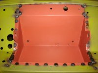
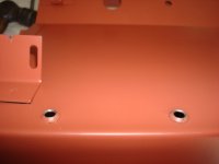
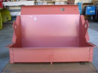
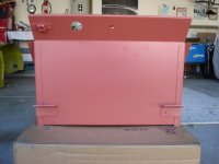
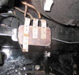
Last week I asked what the difference was between battery boxes the big 3 had. I purchased mine from TRF because I needed one that went all the way up to the cowl. The box I got was a very good replacement. It did have a few problems, spot welds on the brackets on the back were broke on both sides, It does not come with the three wire clamps that are t-shaped, and did not have the two countersunk holes on the back for the overdrive relay. No big problem to fix any of them. If you need to replace your box this is the one I would get.

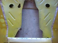
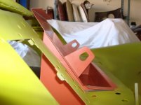
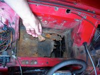
As for the installation I was told by TRF and others that I would need to cut something to be able to fit it in the car. I did not want to do that so I drilled out the two spot welds on the 2" piece of metal infront of the battery box. I then clamped a 2X4 to the piece and bent it down about 1" I used the board so the bend would not have any distortions in it. The box was then pushed down into place without any cutting at all. If you look at the one picture you will see were I drilled out the weld in the bottom corners so I could bend it down.

All of the plug welds were from the bottom except for the ones on the top of the cowl. I will grind them off flat then then put a punch mark that will look like a spot weld next to them. I will do the same on the flange that goes around the top of the box. This was an easy installation it just took a long time.
 

Attachments

  • 16276.jpg
    16276.jpg
    76.3 KB · Views: 596
more pictures
 

Attachments

  • 16277.jpg
    16277.jpg
    77.6 KB · Views: 566
more pictures
 

Attachments

  • 16279.jpg
    16279.jpg
    87.3 KB · Views: 564
more pictures
 

Attachments

  • 16280.jpg
    16280.jpg
    82.4 KB · Views: 560
more pictures
 

Attachments

  • 16281.jpg
    16281.jpg
    94.5 KB · Views: 549
Last one I tried photobucket but it did not work
 

Attachments

  • 16282.jpg
    16282.jpg
    79.5 KB · Views: 548
Nice work. Taking the extra time now will be worth it in the end. Good Job!
 
I use s a Dremil tool with a cutoff wheel and ground out all the spot welds from the top. I did not want to damage any of the metal on the shell.
 
Beautiful job Keith, very helpful photos. I'll be attempting the same thing in the next couple of months, I've ordered the same box. Once you had it roughly in place, how did you push the front flange piece back to where it needed to be?

If you have the camera handy again sometime, I'd like to see a shot under the bulkhead showing the tabs you put in.

Also, please don't tell me those floorpans are original. I need to move to Arizona. And you look like you are hogging more fenders than you need too!

Randy
 
TR4nut said:
And you look like you are hogging more fenders than you need too!

Randy

And who among us isn't? LOL.

That is really nice work Keith - came back to look at it several times already.
 
FYI the two holes in the back of your new battery box down near the bottom corner which are flared one way and for the flat-head screws you have to weld into place for securing the overdrive relay under the dash, up behind the heater.

My new battery box came from England in 1988 and I later found out that the two angles where the dashboard supports are screwed to the back of the battery box were too low or else the repro battery box was about a 1/4" to 3/8" too shallow. Anyway, once it was all together, I had clearance problems where the body for the choke cable was too close and rubbing the bottom of the heater body over near the glove box. Also I had to make an adaptor plate to hold the relay lower because there wasn't enough space for the relay to fit onto these two new flat-head screws I had welded in from the other side. I tried but it wouldn't fit up behind the back corner of the heater. See the adaptor plate which lowered the relay body about 1/2".
 

Attachments

  • 16286.jpg
    16286.jpg
    21.1 KB · Views: 550
Keith,
Looking very good. Bill told me you'd do a 1st class job and get everything as it should be.
 
Randy I have not yet welded the tabs to the box. I think you are talking about the t-shaped tabs. I did not remove them from the original box yet, I may just make new ones. If you need the location I can take some pictures of the original box. To lift the piece of metal in front of the box back up I used the same 2X4 and pushed it back up using to large c-clamps. I put the board under the metal to the front of the car and clamped it down. Then I moved the board to the back and did the same thing over again so the metal would not distort. Then I got a 2X2 piece of wood and clamped it again in the center so I could do my plug welds. I started in the center and worked my way out on both sides. I forgot to mention that I also put a piece 1/4"X2"X14" piece of metal on the top of the front battery box flange so I would not bend the metal when I clamped it down. The plug welds were a bit of a pain because of the tight space and the piece of wood but I wanted to make sure everything was tight.

Don thank you for the information I did not think about the screws. They were not welded on my original box but they may have broke off over time. It would be a pain to replace the relay by yourself without them being welded on. All the measurements I took before and after seemed good. I will see when it all goes back together.
 
Thanks Keith - I think you saved me some time, good instructions and your effort looks great. Yes, I was referring to the t-shaped tabs. On the one rusty box I have for reference I only spotted one tab on the back-side.

Randy
 
OK, where do you learn all that stuff? Professional welder? Mechanical engineer? Former body shop owner?

And, by the way, how will you finish off and seal the edges of that job on the battery box?
 
Where did I learn the stuff, lots of mistakes and still making more. As for the edges I will put on a small bead of seam sealer. No leaks.
 
Thought I'd resurrect this thread as it has been very useful to me, and also to ask a question. I am working on putting a TRF battery box in my TR3A. The previous owner had already cut out most of the old box so I'm prepping the TRF box and looking at what remains on the bulkhead to cut off.

Here's the prep work so far:
IMG_0638640x480.jpg


Like Keith, I had to weld up the back brackets as they were very poorly tack welded on the box. I also added back in the wiring tab that doesn't come with the box. The weld are now solid, but you can probably tell that I should ask for my money back from that welding class I took a couple of months ago. Welding 1/4" steel is fine, but this sheet metal stuff is hard to do.

I plan on using Keith's trick also to bend the front bulkhead lip to get the box in. Which leads to the question: the TRF box comes with a lot more extra metal at the top of the box including the flange for the cowl section. I'm leaning strongly to cutting that off and just tucking the box under the cowl.

Here's the flange I mean:
IMG_0639640x4802.jpg


On the bulkhead, I was thinking of leaving about 1/2" of bulkhead on top to attach to the box:
IMG_0640640x480-1.jpg


I can predrill similar to Keith, then weld from underneath to hide as much of the ugliness.

Has anyone that used a TRF box done a similar thing - in particular cut off that flange section?

Thanks
Randy
 
We had a Saturday morning tech session a few years ago and we replaced a member's battery box. I don't know which supplier it was from. But I remember that two of us with two by fours pushed down on the box (forced it) till it finally popped right into place.
 

Attachments

  • 17131.jpg
    17131.jpg
    93.2 KB · Views: 439
I had a box that I bought from TRF many years ago and used it in my restoration. It had the T-shaped brackets for the wiring harness and the spot welds for the brackets were very good. Maybe TRF's quality on this item is slipping.

After contemplating how to get the box in, I just cut the section out at the front of the box. I replaced with new metal. It was the best decision for me at the time, as I needed the section up to the scuttle as my original was all rotted out, and the front section was pitted. If I had to do it over, I would probabley cut the front section out again. It was pretty quick to do that way, and once the new pieces were welded in, add a little lead and it looks like new...yes, all welded seams on my TR3 are leaded in. :thumbsup:
 
Back
Top