• Hey Guest!
    British Car Forum has been supporting enthusiasts for over 25 years by providing a great place to share our love for British cars. You can support our efforts by upgrading your membership for less than the dues of most car clubs. There are some perks with a member upgrade!

    **Upgrade Now**
    (PS: Upgraded members don't see this banner, nor will you see the Google ads that appear on the site.)
  • When posting a classified ad, you MUST select a prefix from the drop-down next to the subject line. If you don't you will get an error and your ad will not be posted!
Tips
Tips

TR2/3/3A TR 3A Accelerator Bushing Placement

Tinkerman

Darth Vader
Offline
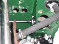
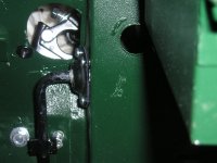
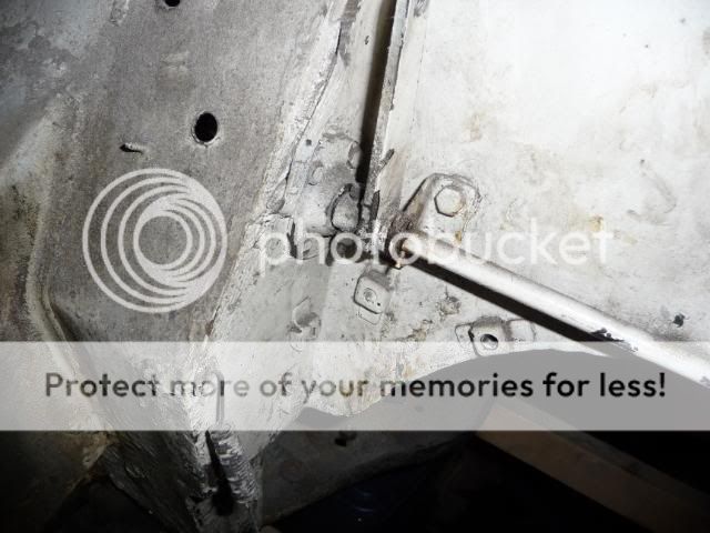
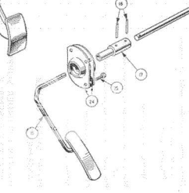
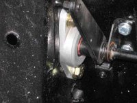
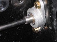
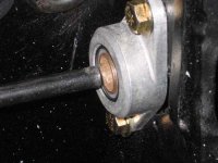
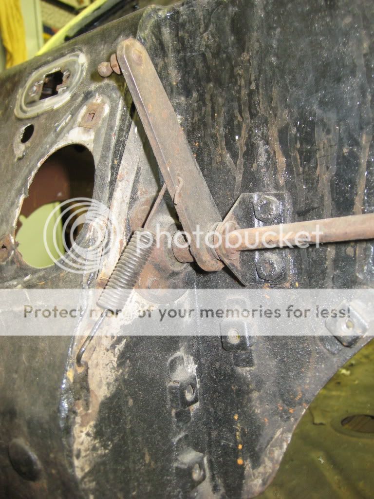
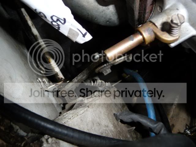
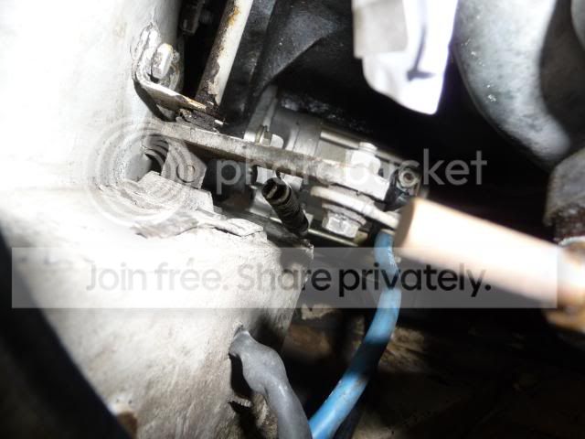
My goal today was to install the accelerator assembly. I have been working with it off and on for the last two weeks. I finally got it installed and I suspect that there is a problem. I was pondering the placement of the bushing holders. I researched everything I had, looked at all the pictures I have but, it was a hidden item everywhere I turned. I figured that it was fifty/fifty on the placement so I rolled the dice and decided to mount them under the dash. See the pics. I suspect I made the wrong choice. So my question is, are they mounted on the outside of the bulkhead, inside or one of each? I will sit here, have a cold adult beverage, contemplate my future as an automotive restorer and await the answer. Scheech, I hate do overs!

Thanks, Tinkerman
 

Attachments

  • 19755.jpg
    19755.jpg
    73 KB · Views: 483
  • 19756.jpg
    19756.jpg
    81.9 KB · Views: 493
The bushing holders are mounted on the engine side of the fire wall. At least that is how they are on my car.
 
Tink,

Just going to run out to the garage and snap some photos. Mine is still on the tub.

BRB.

Cheers,
M. Pied Lourd
 
K. Here are some photos, hope that they help.

P1060672.jpg

P1060674.jpg

P1060677.jpg

P1060679.jpg


Cheers,
M. Pied Lourd
 
Dick: There are bushing retainers at both ends of the cross-shaft. Each retainer consists of an inner and outer plate as shown below.

link1.jpg


link2.jpg
 
Thanks for the PIC's MP, I of course have it wrong. I noticed in the third picture, the white car has a bolt and nut holding the throttle lever on to the shaft. I guess someone got tired of fussing with the mills pin. I will take it out and try to get it right this time, sigh!
Thanks to all of you for taking the time to help me out.

Tinkerman
 
Tinkerman,

I doubt it will matter in the way it functions. Someone will have to look hard and know better and notice. I think I'd let it be. Mine had a bent nail through one side and the holes needed redrilled and new pins installed (I used split pins).

In the 3rd picture, where is the other end of that spring?
 
TexasKnucklehead said:
Tinkerman,


In the 3rd picture, where is the other end of that spring?

The other end of that spring should be attached to the linkage lever. I suspect he undid it at some point along the way.

Tinkerman
 
Right. One end attaches to the linkage. Does the other end have a special attachment point, or does it just go under the inner fender well ?
 
Here's what I wound up doing for the accelerator linkage.

I used a couple of self aligning bushings from McMaster. I did a little re-engineering also. I made a new sleeve where the pins go on the driver's side to connect the cross piece to the pedal. I eliminated the step in the sleeve, and it rides in the new bushing. The pic with the new sleeve doesn't have the pin driven in yet, but to disassemble everything, all I have to do is drive that pin out, then I can extract the pedal from the bushing. You can see that in the last pic. Unbolt the cross piece from the firewall, and you can extract it from the other bushing by pushing into the vacated bushing on the driver's side. Since there's a lot of slop going into that bushing without the sleeve on there, it's very easy to get the cross piece out. IIRC, the ID of the two bushings are different sizes.

The whole system turned out to be very smooth acting.
 

Attachments

  • 19770.jpg
    19770.jpg
    27.6 KB · Views: 354
  • 19771.jpg
    19771.jpg
    32 KB · Views: 356
  • 19772.jpg
    19772.jpg
    30.4 KB · Views: 344
That really looks great Art. I finally got mine in. Still have to put the pin in. So, pin, two self tapping screws and its done. I really like your rig much better. Installing the accelerator assembly has to rank right up there with one of the tougher jobs on the TR 2,3.
Thanks for the pics. I enjoy seeing great craftsmanship!

Tinkerman
 
Yes, it is a tough job, especially when the engine is in place. Although I did all of the work without the engine in, I wanted to make it so <span style="font-weight: bold">when</span> the engine was in, I could get it apart without to much of a hassle if need be. I still have most of my hair left, and didn't want to be subjected to pulling it out because I had to change some accelerator linkage parts. :laugh:
 
It is one of the only things left on my car....kinda dreading taking it out now...looked for the mills pins once...couldn't find them so I gave up temporaily :wink:

Cheers,
M. Pied Lourd
 
Mills pins are now what I call roll pins or split pins. I bought some from MOSS and I could have used one from my assortment bought from several years ago. In fact if you need some let me know I'll send you a couple. I have the original that I took out and it is a solid pin. That's the type I'm familiar with and in fact, I might use it to replace the nail I have in there now. I took it apart and got all of the parts out, after I found that I put it together wrong. I put the rod in with the front bushing back into the car, just checking everything, you know. I could not get the accelerator rod with the pedal back out! I fussed with that for about two hours. Gave up, put it all together and it's done.
Should have done that while the engine was out. On top of all that I had some issues with the drivers side of the side wall. As in not being flat! Had to do some shimming to get it all to work. I'm too far along and could not get a good swing with the hammer to get it all straight.
I really like Art's set up!

I love automobile restoration, that's right isn't it?

Cheers, Tinkerman
 
Here's a pic showing that spring in place, hopefully it is correct as it is also the last thing on the body that I haven't disconnected:
IMG_1217.jpg


The spring attached to a small tab on the body - the spring looks a lot like the spring for the clutch return on the clutch slave.
 
I just dug up a photo of mine before I disconnected it.

P1040024.jpg


P1040025.jpg


Randy, yours looks cleaner than mine!

Cheers,
M. Pied Lourd
 
TR4nut said:
the spring looks a lot like the spring for the clutch return on the clutch slave.
Similar size & length, but the spring for the clutch slave should be a LOT stiffer.
 
Tinkerman said:
Mills pins are now what I call roll pins or split pins.
I could be mistaken, but I believe those are actually 3 different (though similar) things.

A "Mills" pin is solid, with grooves pressed in the sides to give it some bite in the hole (almost like just two lines of knurling on opposite sides of the pin). The grooves are typically deeper towards one end, giving the pin a bit of taper (but not enough to qualify as a taper pin).

A "roll" (or "rolled") pin is actually a thin sheet of metal rolled into a cylinder, so that the ends overlap.

A "split" pin is a somewhat thicker sheet of metal, rolled into a cylinder so the ends don't quite meet.

In some cases, a split pin (which is much more common and cheaper) is an adequate substitute for the other two types. However, a roll pin is more flexible and stronger and will accommodate more variation in hole size than a split pin; while a Mills pin is more rigid than a split pin and stronger then either rolled or split pins.
 
Thanks Randy -and Randall.

As you can see in my picture, the car came with a spring jammed under the fender-well, which didn'd look right to me. The nail wasn't a good substitute for whatever pin should have been in there (mills I assume) and caused the holes to be out of round. I figured a split pin could be used since the sheer strength should not be an issue -assuming the pedal stop is adjusted to the full open throttle position, even though the pedal is bent. I thought of using a cotter pin, but decided to avoid any risk of it coming apart and sticking the throttle. So I drilled the holes larger, drove in a split pin, and mushroomed the ends so it couldn't fall out and painted it.

I also opened up the "bearing" hole on the drivers side a little so the assembled linkage can be fitted without scratching the car or linkage (from the engine bay). -Assuming I ever get to a point where I start putting things back together.

Now I see there is a little tab to atach the proper spring on my car too. I have no idea why it wasn't used, and noticed that little tab when I was working in the engine bay some time ago.
 
That's kind of interesting, Randy's picture shows the ball stud to the left of the linkage lever. On mine the ball stud is to the right of the linkage lever. Easy enough to switch depending on the linkage. My accelerator assembly is not native to my car. It came from Ebay. Mine was a rusty lump so had to go.

Thanks Randall, for the info on the various pins. What I got from Moss were split pins.

Tinkerman
 

Attachments

  • 19773.jpg
    19773.jpg
    89.5 KB · Views: 290
Back
Top