• Hi Guest!
    You can help ensure that British Car Forum (BCF) continues to provide a great place to engage in the British car hobby! If you find BCF a beneficial community, please consider supporting our efforts with a subscription.

    There are some perks with a member upgrade!
    **Upgrade Now**
    (PS: Subscribers don't see this gawd-aweful banner
Tips
Tips

TR2/3/3A TR-3 Fuel Tank Outlet Connection

RC64

Jedi Hopeful
Country flag
Offline
I'm installing a restored fuel tank in my TR-3A and am considering reconfiguring the fuel line connection at the tank outlet. The vendor catalogs and TR-3 Parts Catalog show two 180 degree loops in the line from the tank. Is there a technical reason, other than routing convenience, for having those loops in the line?

I have the Moss fuel line with the proper fitting and ferrule, but I'm concerned about the security of that union. It's the original tank, but the seat in the outlet is a bit rough. As a result, the ferrule isn't compressing as it should.

As a work around I found a 90 degree adapter that matches the threads on the tank and would let me mount the fuel line with a compression fitting parallel to the bottom of the tank. I've seen a photo on the forum in the past with this set up but I can't seem to find it again.

Thoughts anyone?

Rick...

I made up my own fuel line using stainless steel tubing and 90 deg. npt(Ithink 3/8)x 5/16 compression at tank oulet.The fitting fit right through the floor althouth getting the grommet on was a little difficult but it fit and sealed.I would not recommend a standard type compression fitting and ferrule.I used a Swage-lok type with a two piece ferrule.Other brands like Imperial Eastman also make this type which are much more reliable,and expensive, than what I call plumbing olive type.I also used a Swagelok compression panel mount ball valve in place of the standard fuel shut off up front.
Not sure what you mean by loops.I have post 60k car so the line goes straight forward to rear vertical panel behind seat,then down to holes thru frame.
Tom
 
Tom...

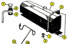
The loops I mentioned are shown here...

fuel line.jpg

This is a clip from the Moss catalog, but the Triumph parts catalog shows the same arrangement. On my pre-60K the tank sits on the floor so with the tank to floor pad the outlet ends up just about flush with the underside of the floor. I should able to use either the set up above, or a 90 degree fitting. There is enough room for the "loops" if they are needed. It would be easier though with the 90 fitting.

I wasn't familiar with the Swagelok technology. You piqued my interest though so I was able to find some excellent information on how they work. I'll have to consider that line on any of the pressure lines in the future. I see they are available through Amazon.

Rick...
 
Tom...

The loops I mentioned are shown here...

View attachment 31465

This is a clip from the Moss catalog, but the Triumph parts catalog shows the same arrangement. On my pre-60K the tank sits on the floor so with the tank to floor pad the outlet ends up just about flush with the underside of the floor. I should able to use either the set up above, or a 90 degree fitting. There is enough room for the "loops" if they are needed. It would be easier though with the 90 fitting.

I wasn't familiar with the Swagelok technology. You piqued my interest though so I was able to find some excellent information on how they work. I'll have to consider that line on any of the pressure lines in the future. I see they are available through Amazon.

Rick...

Hey Rick,It looks like the loop is back up to bottom of floor pan.With the 90 adapter it exits just below the pan ,pointing forward,so no loops necessary,but I think I have a slight kick to come back up to hug the bottom of the pan.I have some sections of rubber fuel ine cut and slipped over to keep it from chafing .My line exits on the left driver side .Not familiar with pre 60k or original type connections.
Mcmaster Carr is also a good source.I used to order a lot of stuff from them for projects at work and was lucky enough to have "left overs" for the TR3.
Tom
 
There are generally two reasons for putting loops like that in steel lines.

1. To allow for easier adjustment during installation to get it to fit properly. When I was in college back in the 60s, I worked on an assembly line that built Fruehauf semi-truck trailers and we had similar loops in the metal air lines that went back to where the rubber brake hoses were connected. It provided more flex for making quicker connections.

2. Stress relief. The loops allow for slight movement of the lines without putting stress at a "single" point, but rather around the entire loop. Even the slightest movement at a single point over many years of driving could cause the line to crack. Example: Take a metal coat hanger and keep bending it back and forth at the same location and see how few cycles it takes to break.

Vila
1933 Chevrolet
1962 Triumph TR4
1984 BMW 633 CSi
 
Interesting...my 1960 model had the fuel tap on the left, and only had the single loop. I see the need for the one coming out of the tap, as the line must come back flush with the body to clear the differential. The second loop is not so obvious.

Wait...I took a look on the car. The second loop would be to follow the upward step that the body makes. It's not obvious in the diagram, but it's not a loop...rather 3 - 90 degrees as it follows the body floor. The first is to route it forward, and the second two 90s are to follow the upward step of the body floor panel.

So, there should be only 1 loop. The rest are bends along the floor. And I agree, if you use a 90 degree coupler, there would be no reson for the loop...except strain relief.
 
Good points from each of you. I was able to locate a 90 degree fitting that would work, but at the same time I was able to figure out how I could make the standard fitting work also. I'll have to climb under the car and take a close look at the best way to route it from the port which on mine is in the center. Of all the photos I've collected from various sources, and the many that have appeared here I don't recall any of the underside in that area. Anyone have a good shot of the area?

Rick...
 
Back
Top