• Hi Guest!
    You can help ensure that British Car Forum (BCF) continues to provide a great place to engage in the British car hobby! If you find BCF a beneficial community, please consider supporting our efforts with a subscription.

    There are some perks with a member upgrade!
    **Upgrade Now**
    (PS: Subscribers don't see this gawd-aweful banner
Tips
Tips

Test light to set static timing

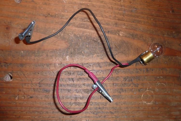
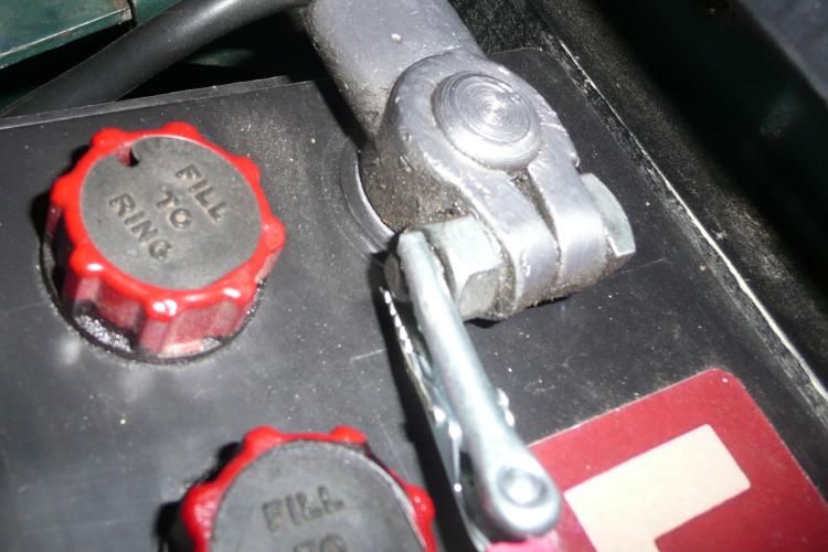
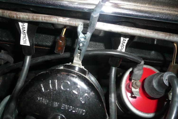
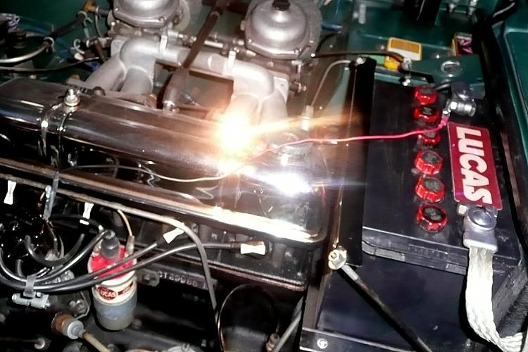
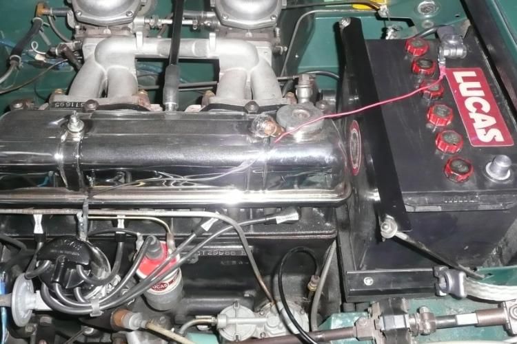
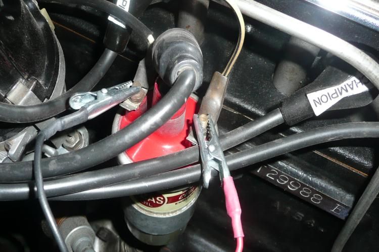
I just went and looked at my car. I have the hole on the pully and the pointer lined up as best I can, but noticed that the points rubbing block is a bit to the right of the corner of the square lobe. It is not right on the corner. Does that mean that the timing marks are not perfectly lined up? Could that be my problem?

Art
 
Sounds like I use Ken's method (light connected to disconnected low tension lead & battery - ignition off) but there are many ways to do this.

A couple of thoughts...

We all tend to assume that the timing marks are correct but it is pretty easy for them to be off (by a little or a lot) depending on the care taken when the front pulley was last mounted to the engine. A mark that's off a bit will give you an innacurate starting point but if the engine runs then it is at least good enough to finish te job 'by ear' or 'seat of the pants'.

The approach you describe -- "I have the hole and the marker lined up and I'm turning the distributor CCW until the light goes out and then CW just until the light goes on" sounds like it will set the timing at TDC so you should be backing that off to about 4° BTDC to get to your starting point (one way is to use the vernier knob on the distributor).

When you move the engine to TDC, i.e. get the hole & the pointer lined up) it is best to do this with the engine rotating in its normal direction (CW as viewed from the front). If you go too far then back it up aways and try again approaching once more from the normal direction of rotation. The reason for this is the likely slack in the timing chain that introduces some slop between the movement of the crank (pulley) and the camshaft (distributor).

At this point (engine will run) I'd be tempted to dial it in better by ear, road test it for any pinging (and adjust if need be) then see what static timing is when all that is done (and make a note of it for future reference).
 
af3683 said:
...the points rubbing block is a bit to the right of the corner of the square lobe. It is not right on the corner. Does that mean that the timing marks are not perfectly lined up?

I think thats normal... i.e. as the points first open the rubbing block has not yet reached the peak of the lobe.

But the relationship of the points & lobe & timing mark is just a function of you moving the distributor so they neither confirm nor deny that the timing marks themselves are accurate (though since the engine runs they must be pretty close).
 
Can someone post two photos showing the test light set up: one with the low tension wire connected (ignition on) and one with it disconnected (ignition off)? VERY BASIC, I know, but sure would be helpful.
 
If your vacuum advance was oriented as in the picture and is now radically different, there is probably something wrong. Try it again. Make sure you are using the TDC mark on the crank pulley and not some random mark. The test light or buzzer method will not work with the ignition switch off or the coil to distrib wire disconnected. Electricity goes to ground thru the circuit of least resistance. When you connect a lite in parallel to the coil to points wire, the closed points provide a near dead short and your lite or buzzer has some resistance, so the juice chooses the points to go to ground. When you open the points, there is no more points circuit, so the juice goes thru your lite.
Bob
 
BTW. It appears that the test lights mentioned here have two wires, with two clips (red and black?). My test light has one wire with red clip and one with a probe. What's the proper way to use this?
 
LexTR3 said:
BTW. It appears that the test lights mentioned here have two wires, with two clips (red and black?). My test light has one wire with red clip and one with a probe. What's the proper way to use this?
What I find easiest is to add a "clip lead" to the probe, so I can connect it to whatever without holding it in place.

https://www.radioshack.com/product/index....lterValue=Leads
 
LexTR3 said:
Can someone post two photos showing the test light set up: ...one with it disconnected (ignition off)?

Here is how the 'ignition off' method works:

Light is just a 12V lamp with leads:

TestLight1.jpg


One end connect to the hot side of the battery:

TestLight2.jpg


The other end to the distributor (with the lead from the coil disconnected):

TestLight3.jpg


That connection could also be made at the other end of the white/black lead itself if the lead was disconnected at the coil end instead of the distributor.

When the points are closed (as they likely will be when this is initially hooked up) the light will be on:

TestLight4.jpg


The distributor is rotated CW until the points open, at that moment the light shuts off:

TestLight5.jpg


Certainbly not the only way, possibly not the best way, but it's simple and it works.
 
The 'ignition on' set-up looks like this:

TestLight6.jpg


Again -- light on = points closed, light off = points open.

The igntion is on so I disconnected the primary lead at the coil to avoid the (remote, but embarrassing) possibility of the engine starting.

In case it isn't obvious, polarity (the red & black leads) is irrelevant here.
 
Randall and George. Many, many thanks for the explanation and the photos.

Now, then... if the lead from the coil to the distributer is NOT disconnected, am I assuming correctly that I should (1) turn the ignition switch on, (2) connect one clip of test light to the positive side of the battery, and (3) touch the probe (or second clip) to the lead (either at the coil or at the distributor) to check the points? Or am I confused....?
 
LexTR3 said:
...if the lead from the coil to the distributer is NOT disconnected, am I assuming correctly that I should (1) turn the ignition switch on, (2) connect one clip of test light to the positive side of the battery, and (3) touch the probe (or second clip) to the lead (either at the coil or at the distributor) to check the points?

That set-up is essentially the 'ignition off' method -- i.e. no need for your step 1.

I disconnected the white/black lead but in fact this is not necessary though it does prevent the engine from firing.
 
George. Thanks....

BTW: Summer has hit here with a vengeance. 90 degrees and about 80 % humidity. Makes me long for Tucson weather. In this weather, I have to ride with the top up or just melt in the car... But life does have its compensations: on the east side of the Blue Ridge Mountains, in a very rural county, there's what's now called "the Brew Ridge Trail." Within the space of about 20 miles, there are four breweries (serving meals also) and several vinyards -- all accessible by beautiful, winding, paved, country roads.
 
Timing Methods


IGNITION "ON" METHOD

Keep lead from coil to distributor connected.
Clip lead from test light to distributor connector noted above & other lead to negative side of the battery (hot).
Turn ignition on.
If test light is on, turn distributor CCW until light goes off. Then turn distributor CW until light just comes on.

IGNITION "OFF" METHOD

Disconnect lead from coil to distributor.
Clip lead from test light to distributor connector noted above & other lead to positive side of the battery (ground).
Do NOT turn ignition on.
If test light is off, turn distributor CCW until light comes on. Then turn distributor CW until light just goes off.
 
Thanks "af3683,

As for clipping the lead from test light to the negative side of the battery (you say "hot"), I have also read that it can be attached to a ground somewhere on the engine.
 
Geo Hahn said:
I disconnected the white/black lead but in fact this is not necessary
It may be necessary, depending on how much current your test light draws and what other loads are connected to the ignition switch. With the points open, current flows through the light, through the white wire and then to ground through the fuel gauge, ignition light, etc.
 
Ed,

I think if you want to attach the lead to ground (or POSITIVE side of the battery) you must follow the rest of the Ignition "Off" Method steps. But I'm no expert and am struggling with this as well which is why I tried to summarize the 2 methods.

Art
 
Am I completely Mixed up (possibly so) but I thought that the positive side of the battery is the "hot" and the negative side is the "ground." So, attaching somethng to the negative side of the battery is the same as attaching it to some grounding place on the engine.

Perhaps someone in the Forum can set us right on this.

Thanks for your input.
 
LexTR3 said:
Am I completely Mixed up (possibly so) but I thought that the positive side of the battery is the "hot" and the negative side is the "ground." So, attaching somethng to the negative side of the battery is the same as attaching it to some grounding place on the engine.

Originally, TR2-TR4 were wired the other way, with the positive terminal of the battery connected to "ground". Many people have chosen to convert; yet many more have not.

So, if it matters, it is best to be clear about which configuration you have. Talking about "hot" (meaning not grounded) and ground instead of plus and minus, is one way to duck the problem.
 
Ah, Randall, as usual you have solved the mystery. Many thanks.

My car is negative grounded, so the positive pole is "hot," or not grounded. Art's car apparently remains positive grounded.
 
TR3driver said:
Geo Hahn said:
I disconnected the white/black lead but in fact this is not necessary
It may be necessary...

Ah ha. When Ed posted a response that had this (white/black) wire still connected I went out to the garage to verify that it would not work like that, only to find that it did. I was pretty sure I had to disconnect it before to get a good result but decided I was just imagining that.

Your 'it may be necessary' is spot on.
 
Back
Top