Hey Guest!

 Hey - did you know if you click on the title of a thread it will take you to the first unread post since you last visited that thread?
 but were afraid to ask:
  STOP!! Never post your email address in open forums. Bots can "harvest" your email! If you must share your email use a Private Message or use the
  smilie in place of the real @
 Pretty Please - add it to our Events forum(s) and add to the calendar! >>
positive_earth
Freshman Member
Offline
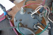
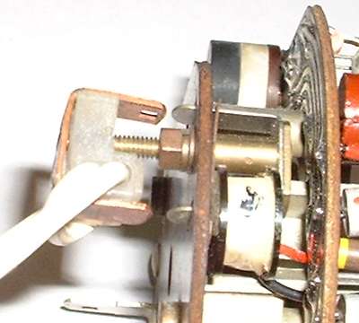
Hey Guys, I'm new here and have a question about Tach wiring. I have consulted many resources and still have not been abble to determine which wires go to which lugs on the back of the tach. Here's some background: 1967 BJ8 3000 Mark III. Car was disassembled and in boxes, so I had no reference during reassembly. The schematic diagrams show 5 main wires : 4 white and 1 green. When viewing the tach from the back there are only 2 terminals, a standard spade type (on the left), and a threaded lug (on the right). I know where the wires come from, and what their purposes are, but I have no idea which terminals get which wires! Seems that all of my resources do not label the above-mentioned terminals...the diagrams I have are poor at best. Can any one post a clear closeup picture, or description? Thanks!