
-
 Hey Guest!
British Car Forum has been supporting enthusiasts for over 25 years by providing a great place to share our love for British cars. You can support our efforts by upgrading your membership for less than the dues of most car clubs. There are some perks with a member upgrade!**Upgrade Now**
(PS: Upgraded members don't see this banner, nor will you see the Google ads that appear on the site.)

Tips
- We have a special forum called "Member Articles" where you can submit actual articles for consideration for publication. Learn More
- Don't have an Avatar? If not, your avatar will default to the 1st character in your username. Go into "Account Details" to change your Avatar.
- Some basic forum navigation info: click
 Hey - did you know if you click on the title of a thread it will take you to the first unread post since you last visited that thread?
- Hey Guest - Is your British Car Club in our Clubs database? If not, send me a PM - Basil

- Looking for a local club? Click the "Clubs" tab above and browse hundreds of clubs world-wide.
- Add Android or iPhone APP: click
- Did you know - any picture or video you add in your posts in any marque-specific forum will also get added to the Media Gallery automatically.
- A few more tips about posting and replying: click
- Hey there Guest - be sure to keep your profile page up to date with interesting info about yourself: learn more
- More tips and tricks on Posting and Replying: click
 but were afraid to ask:
  STOP!! Never post your email address in open forums. Bots can "harvest" your email! If you must share your email use a Private Message or use the
  smilie in place of the real @
- Want to mention another member in a post & get their attention? WATCH THIS

- So, you created a "Group" here at BCF and would like to invite other members to join? Watch this!
- Hey Guest - A post a day keeps Basil from visiting you in the small hours and putting a bat up your nightdress!
- Hey Guest - do you know of an upcoming British car event?
 Pretty Please - add it to our Events forum(s) and add to the calendar! >> Here's How <<
- Hey Guest - you be stylin' Change the look and feel of the forum to fit your taste. Check it out
- If you run across an inappropriate post, for example a post that breaks our rules or looks like it might be spam, you can report the post to the moderators: Learn More
- If you would like to try some different "looks" or styles for the site, scroll to the very bottom, on the left and click the Style Selector.
You are using an out of date browser. It may not display this or other websites correctly.
You should upgrade or use an alternative browser.
You should upgrade or use an alternative browser.
SU fuel pump coil [?] testing...???
- Thread starter timbn2
- Start date


Offline
You could measure the resistance of the coil, between the two leads shown. A good 12 volt coil should read around 3 ohms. A GOOD Ohmmeter is needed. A poor meter may not be able to accurately read very low ohms such as this. If the reading is much higher or lower the coil may be defective. A low reading could mean shorted turns, a high reading would mean an open circuit or break in the wires.
Measure the resistance between the leads & the pump frame. It should show very high resistance. If not, the winding might be shorted to ground internally.
D
Measure the resistance between the leads & the pump frame. It should show very high resistance. If not, the winding might be shorted to ground internally.
D
Offline
Sounds great. It isn't shorted & isn't open circuited. Really nothing more to do with this part of the pump.
D
D
Offline
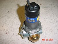
I can't say for sure. Different models had different holes. The one in the enclosed pic has a small air inlet, hose fitting in the lower part for ventilation. It works in conjunction with the fitting on the top left which is a vent with a ball check valve in it.timbn2 said:thank you for the info so far...
one more question...
was there ever a "drain" hole in the body...like this

it looks to clean to be corrosion, but ...???????? i know the one on the bottom left is meant to be there but what about the centered one?
When the pump is operating, air is pumped through the pump to ventilate the contacts. Without some ventilation, the slight contact arcing would cause ionized air to build up around the contacts & increase contact burning. The air inlet is sometimes led to a drier location via small hose so that water does not get into the pump.
I guess on your pump it depends on exactly where the "holes" lead to. In any event, the pump internals need some ventilation.
D
Attachments
Keoke
Great Pumpkin
Offline
Hi Dave,yep after locating the ground connector hole and looking at the original picture that is one of the first stepped end cap pumps. There is no vent in the cap and that center vent must be positioned so it points straight up when the assembled pump is in its correct mounting position. I hope he marked the two halves of the pump before he separated them.This pump should also have the 11 brass armature bearings in it too.---Keoke
OP
timbn2
Jedi Hopeful
Offline
Keoke said:Hi Dave,yep after locating the ground connector hole and looking at the original picture that is one of the first stepped end cap pumps. There is no vent in the cap and that center vent must be positioned so it points straight up when the assembled pump is in its correct mounting position. I hope he marked the two halves of the pump before he separated them.This pump should also have the 11 brass armature bearings in it too.---Keoke
Yep...it has the stepped end cap w/o vent and it also has the 11 brass bearings...
why would the center hole in question need to be oriented upward when mounted? - Tim
also... Moss has the stepped cap listed for replacement pumps ant the flat cap as origional. Any insight or correction?
Keoke
Great Pumpkin
Offline
Hi Bn2
To accommodate any sort of arc protection for the points inside the cap you will be required to use the stepped end cap for clearance of that component. This is case whether you use the original Capacitor or the the more updated diode unit.
The center hole pointing up is just the position it attains when the two pump halves are correctly oriented and it is installed on the car.---------------------Keoke