• Hey Guest!
    British Car Forum has been supporting enthusiasts for over 25 years by providing a great place to share our love for British cars. You can support our efforts by upgrading your membership for less than the dues of most car clubs. There are some perks with a member upgrade!

    **Upgrade Now**
    (PS: Upgraded members don't see this banner, nor will you see the Google ads that appear on the site.)
Tips
Tips

Strom Carb spacer

DNK

Great Pumpkin
Country flag
Offline
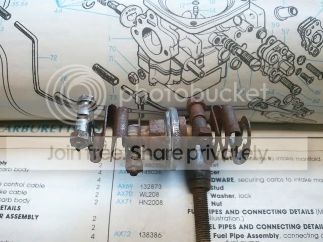
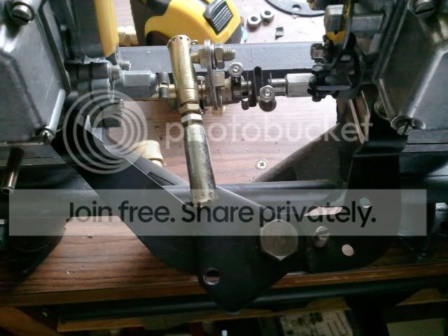
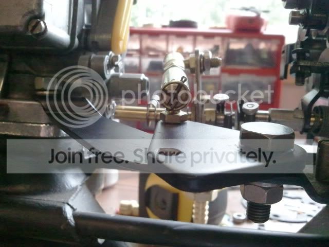
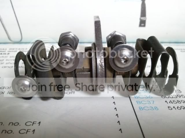
So I learned something new a while ago that you people said. There is a correct way that the spacer and gasket goes on the intake .My question, 2 actually

1.The cut out in the gasket and the spacer is for the hole I have the arrow pointing to . Correct?
2011-07-19133124.jpg


2011-07-19133138.jpg


2.Why is there not a corresponding cut out in the manifold?

3. OK, thought of another one. What does that do?
 
1. Yes.

2. Because the passage was a later emissions modification and only needed to commmunicate with the bore inside the throttle plate. So no cutout needed in the manifold.

3. It's the passage for the bypass (aka gulp) valve. This opens when intake vacuum is very high (eg compression braking), to reduce emissions under those conditions.

When the intake vacuum is high enough, the effective compression is so low that the cylinder may not fire at all and dump raw fuel into the exhaust. If the exhaust is hot, this can often be heard as 'crackling' or popping on overrun as the fuel ignites in the exhaust system. But if the exhaust is cold, the fuel just gets dumped out the back. The bypass valve limits manifold vacuum, to keep the engine running.
 
When did they add this feature?
I also noticed at 2:00 in the carb pic is another hole. Same thing?
 
Sorry, Don, my mistake. The bypass & that port to the manifold were apparently added for the first 'emissions' ZS carbs. I guess it was just easier to not bother with the passage through the manifold.

And I forget what that other hole is, offhand. ISTR it was some sort of drilling for some feature, but I can't think of which one. Maybe someone else has a better memory than I do.
 
Along the same line. I dug out the old couplers in my storage.
Didn't I read it is critical to get them lined up straight (read parallel)
so that they don't bind?
couplingass.jpg
 
You might be thinking about a problem with triples carbs, keeping all 3 throttle shafts lined up. The problem is really aggrivated if a guy with trips is using the heavy duty couplings.
The HD's, don't flex nearly as much as the original type (VB #3-8067) in your picture and as a consequence they put the throttle shafts (especially the middle one) in a bind in certain positions. I noticed it when returning to idle,
I haven't heard any problems with the thicker HD couplings on dual carbs.

But, back to you, Don, just make sure that the nuts or bolt head doesn't hit anything as it rotates with the throttle shaft and personally I like the nut in an up position where I can loosen it easily when sync'ing the carbs.

Your other question:
2.Why is there not a corresponding cut out in the manifold?
Notice that the cut out in the insulator allows the mixture to dump directly into the manifold, It's exit for when the fuel mixture bypasses the throttle when the Throttle Bypass Valve opens.
 
The nut you mention is one of the 4 on the couplers where they attach to the shaft?
 
Yeah those tiny little nuts are the ones you use to tighten the couplers to the throttle shaft. To sync (balance) the carbs, you loosen a coupling so that the carbs are completely independent of one another.
Then when the carbs both suck the same amount of air, you tighten the nut, uniting the throttle shafts to work in unison.
 
Paul talks about the ones on your new car. Are they different than normal?
 
They're the heavy duty such as Richard Good sells. Check them out.
Their thickness makes them less compliant and less flexible,,which defeats the whole point of such a coupling , but after fiddleing with and trying different amounts of the throttle shafts that they bite, they have proven not to be troublesome.. just took patience and experimenting..
In my opinion there's really no neeed for heavy duty couplers, but terms like "heavy duty" and "improved" in any product description always seems to create more sales.
 
I haven't heard any problems with just 2 carbs, but still and all I don't see the need for a heavy duty version, when flexibility is one of the main attributes of this type of coupling.
If flexibility were not a major consideration, the 2 throttle shafts would have (could have) been joined together with a tube like metal sleeve.
 
I can't find a good pic of how the carb linkage all goes to gether does this look right?
2011-07-20132719.jpg


2011-07-20132733.jpg


Got this trick from Paul. But according to this site many of you use sililiar stuff.
CLR
2011-07-20115637jpg2.jpg


See before pic above
 
Front:
100_0213.jpg

Rear:
100_0214.jpg

You also might want to make some preliminary adjustments if you're going to use the stock linkage
For the short vertical control rod with the socket part of the ball and socket joints 3.18 inch from center to center of the sockets
For the long horizonal (which is not in your pictures) 11.94 inches.
Those will get you in the ball park.
 
Thanks Ken, Mine doesn't look like it had the long control rod holder that yours did
 
That fork keeps the spring compressed as the rod moves. In the bottom picture visualize the rod moving to the right when you accelerate.The spring will then compress, the compressed spring seems to help take some of the slop out of the affair and helps it return to position at idle.
 
Very possible. If it broke off or something, you'd probably see some evidence where it was attached to the support bracket.
 
Back
Top