• Hi Guest!
    You can help ensure that British Car Forum (BCF) continues to provide a great place to engage in the British car hobby! If you find BCF a beneficial community, please consider supporting our efforts with a subscription.

    There are some perks with a member upgrade!
    **Upgrade Now**
    (PS: Subscribers don't see this gawd-aweful banner
Tips
Tips

[solved] Sunpro Fuel Gauge... going crazy!

pjsmetana

Jedi Warrior
Offline
I just installed a new Sunpro Fuel Level Gauge in my Spitfire. The stock one was quite beaten up and never read better than 1/2... Plus I'm changing all Dials to red :laugh: When I started her up under full choke the gauge read perfect, as I have a full tank for sure. A few second into running I pushed the choke in to 1/2 (as its about 65F in my garage, and 55F outside) the gauge started going crazy... as in, rapidly moving from full tank to lower than empty. I don't think the choke has anything to do with this, but its the only thing I did after starting. I also tapped the gas to see if maybe the low idle had any effect, and it did not.

I suppose a loose wire could have this effect, so maybe someone has a diagram of where all the fuel level related wires run? Maybe some tips on problematic locations? Also, do I access the fuel tanks level sensor thingy from the trunk side? I'm replacing that too. I pulled the panel from the interior and I didn't see it.

Pictures are greatly appreciated!
 
Re: Sunpro Fuel Gauge... going crazy!

Pete,

The sender is accessed trunk (boot) side.

Does the sunpro gauge use a sender with the same resistance valuesas the smiths unit?

Remeber...the smiths unit is a 10V unit not 12V...
 
Re: Sunpro Fuel Gauge... going crazy!

OK, I found a wiring diagram online for a Mk III Spitfire, and it shows the voltage regulator inline with both the temp and fuel gauges. As <span style="font-weight: bold">Don </span>says, these supply 10VDC to those gauges. However, if it's the original type that came with the car, it's rather crude, and and turns on and off at a rapid frequency to approximate a 10VDC signal. If your new gauge is fast acting, it is most likely emulating this on-off signal. The other thing to consider is if the new gauge is calibrated to work with the resistance of you original sender. Did this new gauge come with instructions?? If so, do they mention anything about the resistance of the sender that is needed to drive this gauge??

If you have to, you can easily eliminate the voltage regulator if the new gauge doesn't require it, but the resistance scale of the new gauge will have to match the sender or it will never work properly.

Edit: BTW, here is the wiring diagram I found. I had to translate a few German words just to make sure of what some of the items were. :laugh:

Edit again: Since you have a 1500, I looked around some more for a later wiring diagram, an it still shows the voltage regulator.

Later diagram...
 
Re: Sunpro Fuel Gauge... going crazy!

The Sunpro instruction are likely to say to connect it to a 12V switched supply. That's because it has its own internal voltage regulation. Most aftermarket (non-Smiths) gauges do not require connection to the Smiths stabilizer and should not be connected to it.

If you connected the Sunpro to the voltage stabilizer, unhook it from the light green wires that are coming from its "I" terminal and make/install a jumper so it is connected to the stabilizer's "B" terminal. The stabilizer's "B" terminal will be switched, fused, 12V power.

As Art said, you have to have the right range sender for the gauge... or buy the right gauge to match your sender. The "nominal" range of the Spitfire sending unit will be about 270 Ohms empty to near 30 Ohms full. That's close to one of the many industry standard ranges for gauges (I think the closest nominal is 240 Ohms = empty to 33 Ohms = full). If you bought a Sunpro gauge that accepts that range and direction you should be OK connecting the sending unit's green/black wire directly to the input terminal on the Sunpro.
 
Re: Sunpro Fuel Gauge... going crazy!

Don_R said:
Does the sunpro gauge use a sender with the same resistance valuesas the smiths unit?

Remeber...the smiths unit is a 10V unit not 12V...

Its just the general sunpro generic fuel gauge. I assume this means 12v, as the instructions that came with it were for 6 different items, none of which were the fuel gauge itself... which immediately gave me a frowny face.

I have a new sunpro fuel level sender that I plan to use.

dklawson said:
...voltage stabilizer, unhook it from the light green wires that are coming from its "I" terminal and make/install a jumper so it is connected to the stabilizer's "B" terminal. The stabilizer's "B" terminal will be switched, fused, 12V power.

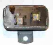
Where the heck is this stabilizer thing? And what does it look like?
 
Re: Sunpro Fuel Gauge... going crazy!

Pete,

The stabilizer is a rectangular metal type unit attached to the back of the Speedo.

I replaced mine with a solid state unit last summer....

There are 2 sets of spades on the regulator...switched 12V and 10V regulated..

Don't remember if I kept the old regulator...


Hope the sending unit has the same diameter as the old one or more fitting and possible gas leaks may occur...
 
Re: Sunpro Fuel Gauge... going crazy!

Pete,

heres a pic of the unit
 

Attachments

  • 19665.jpg
    19665.jpg
    24.3 KB · Views: 796
Re: Sunpro Fuel Gauge... going crazy!

martx-5 said:
However, if it's the original type that came with the car, it's rather crude, and and turns on and off at a rapid frequency to approximate a 10VDC signal.
Just for clarity, the on/off action is not what I would call "rapid". It's slow enough to easily see a test light blink, for example, not much quicker than a turn signal flasher (which is very nearly what it is). And it does take a few seconds to turn off the first time, so this would be entirely consistent with your Sunpro gauge working at first and then "going crazy".
 
Re: Sunpro Fuel Gauge... going crazy!

dklawson said:
If you connected the Sunpro to the voltage stabilizer, unhook it from the light green wires that are coming from its "I" terminal and make/install a jumper so it is connected to the stabilizer's "B" terminal. The stabilizer's "B" terminal will be switched, fused, 12V power.

Don_R said:
The stabilizer is a rectangular metal type unit attached to the back of the Speedo.
There are 2 sets of spades on the regulator...switched 12V and 10V regulated..

Found the stabilizer. That thing sure is in an inconvenient location :smile:

I don't see an "I" or "B" label anywhere on it.

So, read the voltages, and whatever side says 10v, move to the side that says 12v? Sounds like I'm going to be bypassing the regulator completely. Would there be any problem with just removing the regulator, and soldering (or using a butt connector) the dark green wire to the light green wire?
 
Re: Sunpro Fuel Gauge... going crazy!

IIRC, you put in a mechanical temp gauge, so you won't need the stabilizer at all with this new fuel gauge. It also means that you probably have a dangling light green wire that went to the original temp gauge, unless you removed it. That leaves another light green wire that goes from the fuel gauge to the stabilizer. You will need to unhook that wire from the stabilizer and then attach it to the dark green wire(s) on the other terminal of the stabilizer. You can take off the dark green wire(s) from the stabilizer if you want to make the connection easier, because you won't be needing the stabilizer anymore because you have a mechanical temp gauge that doesn't require any electrical input.

Look at the wiring diagram I linked to...the one marked "later diagram" and you will see what we are talking about. Look for the "tach" in the diagram, and the gauges are just below and to the left.
 
Re: Sunpro Fuel Gauge... going crazy!

Pete,

<span style="font-weight: bold">The regulator also provides 10V to the temp gauge</span>..

On my diagram for the 73 Spit it shows that the regulator goes to the tem gauge first then on to the fuel gauge.

They may both go back to the regulator you need to check that on your car..

You will need the the regulator for the temp gauge unless you have changed that out....


Was at the Sunpro site and the sender they show won't fit the stock sender location.
The stock unit is in the side of the tank w/ a lock ring. the Sunpro unit looks like a screw on top mount unit
 
Re: Sunpro Fuel Gauge... going crazy!

TR3driver said:
Just for clarity, the on/off action is not what I would call "rapid". It's slow enough to easily see a test light blink, for example, not much quicker than a turn signal flasher (which is very nearly what it is).

Randall, I've never checked out one of these stabilizers, but if it's as slow as you say, and I'm not doubting that in the least. But, just out of curiosity, what kind of buffering is there in the original gauges that allows this low frequency without seeing the result in needle movement??
 
Re: Sunpro Fuel Gauge... going crazy!

The gauge movement has a resistance wire heater that heats a bimetal strip and the deflection of the strip is what drives the needle. Since the heater has to be electrically isolated from the bimetal strip, it takes some time for the heat to penetrate the insulation, and the (deliberate I assume) result is a gauge that responds very slowly.

When the Stag with the leaking headgasket would overheat, I would literally see the steam leaking from the hood <span style="font-weight: bold">before</span> the temp gauge needle even made it to the red zone!

I was a little surprised myself at how slow the "voltage stabilizer" switches, but I checked several of them and they are all like that.

Don't have the link handy, but someone posted a photo of the mechanism here on BCF a few months back.

Worth noting, perhaps, that not all Lucas gauges work this way. The VS + hotwire gauges were apparently only for the cost-sensitive OEM market; their aftermarket gauges of the period did not require a VS. The aftermarket Lucas temperature gauge I have uses a "balanced" movement rather similar to the fuel gauge in a TR3, which responds practically instantly.
 
Re: Sunpro Fuel Gauge... going crazy!

pjsmetana said:
I don't see an "I" or "B" label anywhere on it.
It's usually stamped into the phenolic base (the brown part behind the terminals); but I've also seen units that don't have either label.
<div class="ubbcode-block"><div class="ubbcode-header">Quote:]So, read the voltages, and whatever side says 10v, move to the side that says 12v? Sounds like I'm going to be bypassing the regulator completely. Would there be any problem with just removing the regulator, and soldering (or using a butt connector) the dark green wire to the light green wire? [/QUOTE]
You can't read 10v, the output switches between 0v and full battery voltage. But usually the connectors are opposite gender, so you can just pull them both off of the VS and plug them into each other. Add some insulation and support, should be good to go.
 
Re: Sunpro Fuel Gauge... going crazy!

Randall,

That may be possible BUT..if the wiring goes from regulator to Temp to Fuel, that will put 12V on the temp guage.

If both guages run back to the regulator..pulling the 12V switched side and connecting it to the fuel sender drops the power to the temp guage.

the best solution is to run a new wire from the fuel gauge back to the 12V switched side of the regulator
 
Re: Sunpro Fuel Gauge... going crazy!

That is true, Don, <span style="font-weight: bold">if</span> he is retaining the original temperature gauge. My understanding is that it is already gone, and so no longer needs to be connected to the VS.
 
Re: Sunpro Fuel Gauge... going crazy!

TR3driver said:
That is true, Don, <span style="font-weight: bold">if</span> he is retaining the original temperature gauge. My understanding is that it is already gone, and so no longer needs to be connected to the VS.

Well, its not gone <span style="font-style: italic">just yet</span>... but yes I have the new sunpro mechanical temp gauge and am just waiting on the adapter from the mini parts site. It should be here tomorrow.

TR3driver said:
... pull them both off of the VS and plug them into each other. Add some insulation and support, should be good to go.

Roger that Randall :smile: gonna go give it a shot now.
 
Re: Sunpro Fuel Gauge... going crazy!

Bingo! Works perfectly now :laugh: Thanks everyone!
 
Re: Sunpro Fuel Gauge... going crazy!

$20 under everyone's pillow should be fine
 
Re: Sunpro Fuel Gauge... going crazy!

DNK said:
$20 under everyone's pillow should be fine

I'll be sure to let the tooth-fairy know she's gonna be working for me now. I hope she can carry that many quarters!
 
Back
Top