• Hey Guest!
    British Car Forum has been supporting enthusiasts for over 25 years by providing a great place to share our love for British cars. You can support our efforts by upgrading your membership for less than the dues of most car clubs. There are some perks with a member upgrade!

    **Upgrade Now**
    (PS: Upgraded members don't see this banner, nor will you see the Google ads that appear on the site.)
Tips
Tips

She breathes again!!!

richberman said:
Randy Forbes said:
Big Step, Rich; you're on your way.

The only Healey I ever worked on (Patricia Dewitt's BJ8, circa 1978... you always remember the bad ones...) that wouldn't shut off had the horn wire inside the steering column melted/shorted to the turn signal feed (keeping it hot all the time). That car, still with its original generator, could be shut off via the battery cut-off switch.

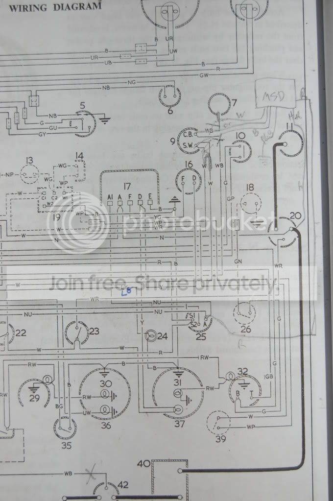
Yours has got to relate back to the alternator conversion. I have the MSD too, wired as per their instructions for a point-trigger (also negative ground) and do not have any run on issues.

But still, <span style="text-decoration: underline">congratulations</span>, and say HI to Bob for me!

No steering harness on the car yet. The alternator conversion was confusing. I had three different diagrams and all were different. See my final pics and please comment if you see something off. I gutted the voltage regular and used it for connections only.

thanks,
rich
There's a hige variety of Alternators and they have different wiring criteria. Did you use a kit from a vendor?
 
57_BN4 said:
Hi Rich,
actually after thinking about it a bit more, the fuel pump won't run off the excite voltage from the alternator so it probably isn't that. Pulling off the MSD key wire should kill the engine, if it doesn't then there is an issue with the MSD.

The ACR alt wiring should be very simple: the big wire goes straight to the battery (usually the starter solenoid +ve terminal) and the small wire goes to the dash charge bulb.

Andy.

Andy,
I think you're right on it. I will try to pull the MSD wire to see if it kills the engine. You're wiring description is how I have it. If pulling the wire works then I'll add the diode to see it the problem is solved.
thanks a million.
rich
 
57_BN4 said:
Hi Rich,
actually after thinking about it a bit more, the fuel pump won't run off the excite voltage from the alternator so it probably isn't that. Pulling off the MSD key wire should kill the engine, if it doesn't then there is an issue with the MSD.

The ACR alt wiring should be very simple: the big wire goes straight to the battery (usually the starter solenoid +ve terminal) and the small wire goes to the dash charge bulb.

Andy.

Andy,
More info. I just started it up after having placed the diode inline between the alternator and warning lamp and the car still doesn't stop when the ignition key is turned off. When I pulled the red wire lead off the ignition key, the MSD shuts down the car uneventfully. So I'm thinking next test is to connect a ballast resistor from the red MSD lead to ground as indicated in the instruction manual and see if that works....
also found a coolant lead at the heater box....glad I found it before the car is together more.
rich
 
Hi Rich,

Sounds like you are getting close to solving it.

Now that you can at least stop the engine by pulling off the MSD wire, perhaps try running it briefly without the fanbelt and see if it then stops as this will completely eliminate the alternator. If it still keeps running even with no alt charging then put a test light on the ignition key switch and see if it stays at 12V when the engine stops. Could be a faulty key switch or some other completely random thing like a mis-wired indicator relay box... Kind of running out of things that could cause the problem.

Andy.
 
57_BN4 said:
Hi Rich,

Sounds like you are getting close to solving it.

Now that you can at least stop the engine by pulling off the MSD wire, perhaps try running it briefly without the fanbelt and see if it then stops as this will completely eliminate the alternator. If it still keeps running even with no alt charging then put a test light on the ignition key switch and see if it stays at 12V when the engine stops. Could be a faulty key switch or some other completely random thing like a mis-wired indicator relay box... Kind of running out of things that could cause the problem.

Andy.

Do I really need to pull off the belt to test this? Can't I just pull off the wire leads to the alternator? And can't I just test across the key switch with my multitester?

Rich
 
richberman said:
Do I really need to pull off the belt to test this? Can't I just pull off the wire leads to the alternator? And can't I just test across the key switch with my multitester?

Rich

Yup, will work equally well on both counts. Might be safer for the alt regulator to take just the small wire off as they do self excite when the revs get over about 2000 and they don't really like running without the battery connected.

Andy.
 
Andy,
The story gets a bit stranger. I added a diode between the small alternator wire and the warning light to prevent backflow. It changed nothing. The warning light still lights when the alternator is not running and goes out when it it running.

The I tested the ignition key switch and it seems fine. When the key is off, there is no continuity across the switch and when it's on there is. When the battery cutoff switch is on the ignition key switch tests at 12.71 volts to ground.

So I added a ballast resistor onto the red MSD wire with the other end grounnded to the chassis (as show in the diagram, although mine was not a dual resistor) and tried that. All I got was some smoke coming from the ceramic block of the resistor and the engine still won't shut off until I pull the red lead from the key switch. I attempted to test the voltage across the key switch while it was running but my meter just jumped and flashed all over the place. I'm not sure what it was doing, but it was not 12 volts.

I wonder if the voltage is coming from the brown/blue (NU) wire which used to attach to the A1 lead of the voltage regulator, as this is now wired to the alternator output via the lighting switch (25) on my wiring diagram. I'm attaching a picture of my MSD wiring for your review. The only modification I mad was to splice the two white wires which usd to attach to the SW coil terminal. This should give me power via the white wire to my ignition key. Why does the NU wire from the lighting switch (25) go back to the ignition key switch(22)?

DSC_00143.jpg
 
Hi Rich,

Thanks for the pic, now I can see hopefully what is going on. The NU wire used to come from the A1 terminal on the reg and is actually the same as the N wire (battery power) except for a few turns around the regulator bobbin inside the reg which compensates the charging voltage for accessory loads like headlights. Now that you have eliminated the reg, you need to connect the NU and N wires together permanently.

The NU wire goes to the Ign switch as its power feed, and the white wire side is the switched supply to the Ign coil and things like the OD relay.

So on that basis, connect the N and NU circuits together and reconnect the small red wire from the MSD to the white wire that used to go to the coil SW terminal. Leave the two white wires joined there.

The reason your resistor is smoking is because it is connected straight across 12V. I don't think you need the resistor but leave the diode in the alt light wire.

Andy.
 
So what I did wrong was I connected the red MSD wire to the NU side of the ignition key switch rather than to the white side?

My NU and N wires are all connect...you can see that in my pictures above.

Should the NU/N have power prior to starting the engine? I think my white wire does as the fuel pumps start clicking on when I turn the key.

rich
 
Hi Rich,

Yep, the white wire is the one that is switched on/off with the key. The N & NU wires are connected to the starter solenoid power cable (20) and so are live whenever the iso switch is on in the boot. There are no fuses in these circuits.

A small point of order about the alternator- if you are using the factory style wire for the output terminal, check that it doesn't get hot when under full charge (half flat battery, 3000rpm). The original genny did about 22A and you will probably see 45 or greater depending on the alternator model. Maybe check with the wiring loom supplier on what the wire in that circuit is rated to or alternatively add another wire between the second output terminal straight to the starter solenoid power terminal.

Andy.
 
57_BN4 said:
Hi Rich,

Yep, the white wire is the one that is switched on/off with the key. The N & NU wires are connected to the starter solenoid power cable (20) and so are live whenever the iso switch is on in the boot. There are no fuses in these circuits.

A small point of order about the alternator- if you are using the factory style wire for the output terminal, check that it doesn't get hot when under full charge (half flat battery, 3000rpm). The original genny did about 22A and you will probably see 45 or greater depending on the alternator model. Maybe check with the wiring loom supplier on what the wire in that circuit is rated to or alternatively add another wire between the second output terminal straight to the starter solenoid power terminal.

Andy.
Thank you sooooo much!!!
 
Andy,
Since I now have a good electrical ear, could I trouble you for a wiring guide/diagram for changing my headlights to a relay activation system which will also turn off when the ignition key is removed. I always loved that feature on my Toyotas and Volvos...never have to find a dead battery due to headlight drain. Should I also put my horns on a relay? I have 6 relays in a box.
thanks,
rich
 
Hi Rich,

Well... I guess it depends on how complicated you want to get. Adding a relay to activate the lighting circuit is relatively easy but it isn't a 'headlight relay' as such. If you want to add a headlight relay then there are plenty of discussions in the archives e.g.
https://www.britishcarforum.com/bcforum/ubbthreads.php/topics/805667/Re_BJ8_headlight_relay If you do fit a headlight relay then you can remove (and crimp together/insulate) the NU wires from the lighting switch and feed the switch straight from the W ignition circuit to get the lights coming on with the key.

If you don't want to go that far then a regular 20A relay under the dash will activate the lights off the key. Remove the two NU wires from the light switch and connect them to terminal 30 on the relay. Then connect terminal 87 to the lighting switch where the NU wires were, using a similar size wire. Connect terminal 86 to the W side of the ignition switch and terminal 85 to the B circuit or a good ground point. Some relays won't have an 87a terminal.

relaywiringguidepz8.jpg


Just a word of caution- having the headlights go out while towing a boat through a twisty mountain pass in the middle of the night is one of the few things that has truly scared me, even though I was a passenger and we were in a modern car at the time. If you plan on driving out of town at night then be very sure your wiring skills are up to the task.

Andy.
 
57_BN4 said:
Hi Rich,

Well... I guess it depends on how complicated you want to get. Adding a relay to activate the lighting circuit is relatively easy but it isn't a 'headlight relay' as such. If you want to add a headlight relay then there are plenty of discussions in the archives e.g.
https://www.britishcarforum.com/bcforum/ubbthreads.php/topics/805667/Re_BJ8_headlight_relay If you do fit a headlight relay then you can remove (and crimp together/insulate) the NU wires from the lighting switch and feed the switch straight from the W ignition circuit to get the lights coming on with the key.

If you don't want to go that far then a regular 20A relay under the dash will activate the lights off the key. Remove the two NU wires from the light switch and connect them to terminal 30 on the relay. Then connect terminal 87 to the lighting switch where the NU wires were, using a similar size wire. Connect terminal 86 to the W side of the ignition switch and terminal 85 to the B circuit or a good ground point. Some relays won't have an 87a terminal.

relaywiringguidepz8.jpg


Just a word of caution- having the headlights go out while towing a boat through a twisty mountain pass in the middle of the night is one of the few things that has truly scared me, even though I was a passenger and we were in a modern car at the time. If you plan on driving out of town at night then be very sure your wiring skills are up to the task.

Andy.

Andy,
If I use the headlight relay as described on https://healey6.com/Technical/Let%20there%20be%20REAL%20Light.pdf,
how do I wire in the ignition switch so that the ignition switch AND the headlight switch needs to be on?
thanks again.
I will NOT tow any boats in the dark with my Healey!!! That does sound scary. Who did the wiring on that vehicle?
 
Hi Rich,

You can take out the NU wires from the lighting switch and join/tape them together so the NU circuit stays intact, then run a wire from the W side of the ignition switch to where the NU wires used to go on the lighting switch. This will mean the current for the side and license plate lamps goes through the ignition key but since you don't have the ignition coil current going through it there is no increase in load on the key switch.

The tow vehicle was a Holden Commodore and the dimmer switch on the steering column chose to fail at that very moment. Completely standard wiring, just bad luck I guess. After a quick stop for fresh underpants we discovered that the low beam still worked fine.

Andy.
 
Andy,
Thanks. I'll let you know how it works out once I wire it up. I also got halogen front lamp conversion kit.
rich
 
Back
Top