• Hi Guest!
    You can help ensure that British Car Forum (BCF) continues to provide a great place to engage in the British car hobby! If you find BCF a beneficial community, please consider supporting our efforts with a subscription.

    There are some perks with a member upgrade!
    **Upgrade Now**
    (PS: Subscribers don't see this gawd-aweful banner
Tips
Tips

GT6 Rewiring Question

UmmYeahOk

Jedi Warrior
Offline
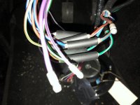
Bought a complete kit from British Wiring. Seems like I’m having trouble with everything I didn’t take a “before” picture of. I am stuck on the steering column. I think I have everything correct except I’m stuck with two purple wires and a brown. Does the Brown/Red go into both the solid purple and purple/black? That doesn’t seem right.

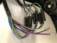
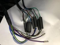
Looking at my original wiring harness, it’s the same. A purple and a purple/black going into an unknown.
 

Attachments

  • 32F2FBBD-4685-4DA2-AF9C-80BC34FCCD0E.jpg
    32F2FBBD-4685-4DA2-AF9C-80BC34FCCD0E.jpg
    51.2 KB · Views: 101
Tomorrow I will give your question more thought.

Lucas wiring follows a standard where various color codes are used exclusively for various functions regardless of whether you are driving an MG, a Triumph, or something else. Knowing the color codes can help sort out a lot of troubles. The two links below are good color code references that should help you sort the wiring problems.

https://www.mgb-stuff.org.uk/colourcodes.htm
and
https://www.ovtc.net/uploads/9/5/1/6/9516577/wiring_colour_codes.pdf
 
Unfortunately, Triumph took color codes more as a suggestion than a law. I've got a GT6 diagram that appears to show several interconnections of different colors. My suggestion would be to get busy with some sort of continuity tester (DMM on ohms scale, powered test light, whatever you've got) and identify where each wire runs.

This diagram is hard to read (very small), but it seems to show a brown wire to the low/high/flash switch joined to a purple wire from the fuse block. The switch was probably made with the intention of using unfused power (brown) for the "flash to pass" feature, but someone decided to change it to fused power (purple) without modifying the switch.

It also seems to show a brown/red (?) coming off the same switch, joined with another NR and a RG that runs over to the fuse block.

I've also sometimes seen replacement parts with different color wires than original. So I would probably start by identifying the 5 wires coming off the low/high/flash switch (by which ones show continuity in each switch position) and then see that they get wired where it makes sense.
 
Purple/black would be the horn and Randall has the rest figured out. Brown to power light switch on dash with the red/green going over to the fuse box to power the parking lights and interior lights (white/red).
The door switch for interior lights has a purple/black wire also. Any wire with a main color and a black strip is going to a switch that is activated by a ground, most are switched power ie lights, heater, wipers and such.
Most of the modern computer controlled cars have relays with controlled ground to operate.
 
Ok, well, I think that just made me more confused. Right now, I have everything plugged into what I thought matched. To fuse is on the left, to steering wheel is on the right. Did I do that wrong? Purple and Purple/black (to fuse) don’t connect up to Brown/Red (steering)?
 

Attachments

  • 2633B9FB-ADB0-4402-BA09-0F06C422587B.jpg
    2633B9FB-ADB0-4402-BA09-0F06C422587B.jpg
    55.8 KB · Views: 98
  • 83E8AB76-86DD-442E-B4D1-26A61D1E7D79.jpg
    83E8AB76-86DD-442E-B4D1-26A61D1E7D79.jpg
    47 KB · Views: 103
Find the horn button off the plate in the steering column, that is your horn button wire, but it goes to a horn relay on the firewall along with the purple wire, read the wiring on the relay letters and numbers.
You have to figure the power to the headlights from a brown wire to the switch on the column, which may turn into a solid blue at that junction into the switch, then out would be to blue/white or blue/red .
Sorry for confusing you, don't have a diagram in front of me.
 
There should be another wire, PB by the diagram, that comes from the slip ring for the horn. I don't see it in your photo, so you may have to take the column apart to find it (or possibly it got removed at some point and you'll need to run another wire).

One of the brown wires from the dip switch should have a tracer. I can't tell for sure, it might be the one on the right in your photo. It should show continuity to one of the blue/white wires, only when the lever is in the high beam position. That brown wire should go to a 4-way, with the NR from the harness and also a RG. Again, you might have to do some sleuthing; the harness wire that my diagram shows as NR (I think, hard to read) should run off to the main headlight switch and be hot only when the switch is set to turn on the headlights. The RG harness wire should run to the fuse block, where it powers the tail lights through a fuse.

The purple wire should connect to the other brown wire from the dip switch. That brown wire should show continuity to the other blue/white wire, only when the lever is pulled for "flash to pass".
 
Did a little research on the solid blue wire and it should come right from the switch and like I said the brown wire supplies the power , but it's at the switch. It would not be unusual for the switch to be bad and not transfer the 12V's to the blue wire. Check the switch on that part.
Randall and I both are wondering where the purple/black wire is off the contact plate.
 
Thanks everyone. I think I got it, but before I test to see what works and what doesn’t, I have one last ground wire to connect, but I can’t figure out where it goes. The length means it has to be very close. Every ground bolt I touched, I hand torqued it back on, but very loose. None of these are loose. The one directly on the steering control arm is too fat to fit, and every other bolt is torqued way too tight (probably for good reason). Any ideas? I’m assuming the motor mount bolts are also too fat.
 

Attachments

  • A091EFD5-CD1A-49DD-8FB4-A540A0898BB5.jpg
    A091EFD5-CD1A-49DD-8FB4-A540A0898BB5.jpg
    76.8 KB · Views: 94
If it has a small loop on it, check the back of the gauges, they need a ground wire for the lights lots of times as the gauge clamp doesn't always make a good ground, especially on a wooden dash.
Goes under the thumb tightening nut.
 
Oh, this is in the engine bay. That loop can only connect to something nearby. Is there a ground bolt on the frame somewhere? It’s taken me so long because I had to make new head and tail light connectors. But all I need now is to add the fuses, the last ground, and reconnect the battery, then I should be able to see what I got right and what I got wrong.
 
Make sure before you hook up the battery to pull all the fuses and see if you get a spark with just touching the positive cable. I like to put a 5 amp fuse in line with the battery cable as I check out all the newly connected wiring. Then add one fuse at a time to ensure none of the smoke gets out!
Cheers from Scott in CA
 
Thank you, but right now everything’s installed. Everything worked... ...until I reassembled the interior. Now, with the key turned on power does not go to the two top fuses. Sometimes it does, and sometimes it doesn’t. One of those times, the interior blower fan kicked on and I couldn’t turn it off at the switch. Also, the temp gauge light doesn’t work, when it did before officially installing it into the dash.
 
Last edited:
Back
Top