• Hi Guest!
    You can help ensure that British Car Forum (BCF) continues to provide a great place to engage in the British car hobby! If you find BCF a beneficial community, please consider supporting our efforts with a subscription.

    There are some perks with a member upgrade!
    **Upgrade Now**
    (PS: Subscribers don't see this gawd-aweful banner
Tips
Tips

Relay question

JPSmit

Moderator
Staff member
Silver
Country flag
Offline
I bought 3 relays today - headlights/ horn and driving light.

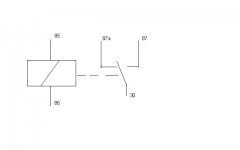
I just want to confirm the wiring. On the relay the following is printed

Am I correct that 85 and 86 are the actual circuit ( eg. the lights) with the relay completing the circuit.

then, if 30 were power, either 87a or 87 could be used to complete the circuit for the switch.

there are five prongs and I presume one (87 or 87a) goes unused.

Is this correct?
 

Attachments

  • 12366.jpg
    12366.jpg
    8.1 KB · Views: 130
No this is not correct.
Terminals 86 and 87 are the power and ground for the coil of the relay. Terminals 30, 87a or 87 are the connections for the circuit you are controlling ie. headlights. Terminal 87a is the normally closed contact (assuming the diagram is correct) and rarely used and 87 is the normally open contact.
The relay function is as follows. Turning on the light switch powers the relay thus closing the number 87 contacts and thus powering up the lights.
Hope that helps. :thumbsup:
 
I think Roman made a typo at the beginning. He meant to say Terminal 85 and 86 are power and ground for the coil of the relay. So your existing circuit in the car powers this. Your new isolated circuit goes through 30 and 87.
 
:iagree:

I read Roman's post twice and scratched scalp... then scrolled to Trev's.

85~86 is indeed the control device (switch, knob, gizmo) power and ground, working voltage in at 30 and load on 87 (or 87a if you want power thru the relay when in the "unpowered" state).
 
I love these boards! thanks all.
 
No worries - thanks all for your answers, This afternoon I will simply wire in the unused switch on the stalk for the driving light and then install the relays closer to the lights. I also realize I need one more relay as I have one for the headlights when I should have two (low beams/ high beams)

Did want to mention what some of you likely already know but what was helpful to me. First off, this article was very helpful

https://www.danielsternlighting.com/tech/relays/relays.html

in the article it said:

"Those seemingly random numbers on relays and sockets are universal (by Bosch decree...) terminal designators. On relays, we have:

86 is the relay switching (control) circuit input.

85 is the relay switching (control) circuit output.

30 is the power circuit input.

87 is the power circuit output.

The best relays to use in setting up a headlamp circuit have dual 87 terminals. That lets you use one 87 terminal to power the left filament, and the other 87 terminal to power the right filament in whatever circuit you're building (low beam, high beam, fog lamp, etc.). Note that a terminal labelled 87a is not the same as an 87 terminal."

it is helpful to me to know those numbers are standard

thanks again all
 
Relays are fun that way.
When I recently had trouble with my brake switch I dug around in my stuff because I knew I had one spare relay for my electric rad fan.
Sure enough, found it - hooked it up & now have good brake lights!
Two identical relays mounted next to each other on the sidewall, looks pretty cool too.
 
Back
Top