Hey Guest!

 Hey - did you know if you click on the title of a thread it will take you to the first unread post since you last visited that thread?
 but were afraid to ask:
  STOP!! Never post your email address in open forums. Bots can "harvest" your email! If you must share your email use a Private Message or use the
  smilie in place of the real @
 Pretty Please - add it to our Events forum(s) and add to the calendar! >>
GTP1960
Jedi Knight
Offline
Conundrum: Which illustration is correct?
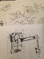
In this pic; the upper illustration is from a Moss catalog.
notice the linkage connects from the back of the shock absorber arm.
that's how mine was & it required me to remove the spring plate before I could remove the lower linkage bolt. (But mine could not have worked any other way, due to the overall system design)
the other (bottom) illustration is from the workshop manual & it shows the linkage arm to be reversed, attaching to the shock absorber arm from the front.
Could this be from an earlier or later design.
The S.A's. are slightly different as well, with the fill cap on the top of the workshop illustration.
appreciate your thoughts.