
-
 Hey Guest!
British Car Forum has been supporting enthusiasts for over 25 years by providing a great place to share our love for British cars. You can support our efforts by upgrading your membership for less than the dues of most car clubs. There are some perks with a member upgrade!**Upgrade Now**
(PS: Upgraded members don't see this banner, nor will you see the Google ads that appear on the site.)

Tips
- We have a special forum called "Member Articles" where you can submit actual articles for consideration for publication. Learn More
- Don't have an Avatar? If not, your avatar will default to the 1st character in your username. Go into "Account Details" to change your Avatar.
- Some basic forum navigation info: click
 Hey - did you know if you click on the title of a thread it will take you to the first unread post since you last visited that thread?
- Hey Guest - Is your British Car Club in our Clubs database? If not, send me a PM - Basil

- Looking for a local club? Click the "Clubs" tab above and browse hundreds of clubs world-wide.
- Add Android or iPhone APP: click
- Did you know - any picture or video you add in your posts in any marque-specific forum will also get added to the Media Gallery automatically.
- A few more tips about posting and replying: click
- Hey there Guest - be sure to keep your profile page up to date with interesting info about yourself: learn more
- More tips and tricks on Posting and Replying: click
 but were afraid to ask:
  STOP!! Never post your email address in open forums. Bots can "harvest" your email! If you must share your email use a Private Message or use the
  smilie in place of the real @
- Want to mention another member in a post & get their attention? WATCH THIS

- So, you created a "Group" here at BCF and would like to invite other members to join? Watch this!
- Hey Guest - A post a day keeps Basil from visiting you in the small hours and putting a bat up your nightdress!
- Hey Guest - do you know of an upcoming British car event?
 Pretty Please - add it to our Events forum(s) and add to the calendar! >> Here's How <<
- Hey Guest - you be stylin' Change the look and feel of the forum to fit your taste. Check it out
- If you run across an inappropriate post, for example a post that breaks our rules or looks like it might be spam, you can report the post to the moderators: Learn More
- If you would like to try some different "looks" or styles for the site, scroll to the very bottom, on the left and click the Style Selector.
You are using an out of date browser. It may not display this or other websites correctly.
You should upgrade or use an alternative browser.
You should upgrade or use an alternative browser.
Question on OD wiring harness 57 Smallmouth
- Thread starter bnw
- Start date
Marvin Gruber
Yoda
Offline
Wiring from the trans goes underneath and up to a relay in the engine bay, then in through the bulkhead to the sw on dash.
Marv
Marv
Don Elliott
Obi Wan
Offline
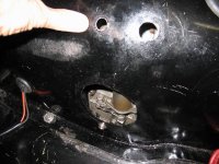
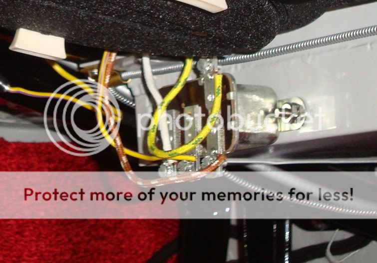
The cables from the top of the gearbox and for the solenoid come through the steel wall of the tunnel near your heel for the gas pedal. It's the grommet closest to the left of the photo. The other holes are for access to the solenoid from the top. Two holes up high for a very long screwdriver and the large hole to see what your doing and to replace the solenoid. This large hole is filled with a rubber plug also used in the floor pans for the floor jack.
Attachments
Don Elliott
Obi Wan
Offline
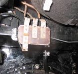
My overdrive relay is mounted up under the battery box. It came that way in 1958 when I bought my TR3A brand new.
BTW, the 2 wires from the grommet shown above go in a sheath or vinyl spagetti tube along the floor under the carpet and then up vertically beside the gas pedal right against the firewall in the corner behind the RHS of the gas pedal.
BTW, the 2 wires from the grommet shown above go in a sheath or vinyl spagetti tube along the floor under the carpet and then up vertically beside the gas pedal right against the firewall in the corner behind the RHS of the gas pedal.
Attachments
TR3driver
Great Pumpkin - R.I.P
Offline
Don is correct, as usual. But I don't like having the wires through the side of the tunnel like that, so mine run up the firewall inside the engine compartment and through the grommet visible to the left in Don's second photo above. The grommet in the tunnel is replaced with a plain plug.
Also worth noting, perhaps, that none of the published wiring diagrams match the original wires on TS39781LO. The diagrams show a wire from the isolator switches directly to the dash operating switch, but TS39781LO had the wire from the isolator switches to one side of the relay coil, then the other side of the relay coil to the dash switch. Function is the same, but there is one less wire from the relay to the dash.
I considered adding holes as Don has done; but in all the years I've driven an A-type, I've only had two solenoid failures. And I prefer to avoid the "swiss cheese effect" if possible.
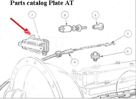
Is it possible that the overdrive relay is installed upside down. The TR3 operations manual shows the 3 terminals in the down position. Apparently the Vanguards had the 3 terminals pointing up, and Laylock used a saloon car for illustration in their manual.
Robert
Robert
TR3driver
Great Pumpkin - R.I.P
Offline
It has been too long, I don't recall for certain; but I think that TS39781LO had it mounted the other way over. Certainly that is the way it is shown in both the TR3 service manual and the OD service manual. (The OD service manual also shows it the other way for the saloon.)
Don Elliott
Obi Wan
Offline
Doesn't matter to me. It works. It's the original relay that was in the TR when I bought it brand new in May, 1958. I checked my sketches as I was taking it apart in 1987 and can't find any sketch for this. In 1990, that's the way I put it back in and I don't think any TRA or VTR judge ever took off a point because of this.
So, it'll probably stay that way for another 22 years. I'll let you know then if I have changed it around.
So, it'll probably stay that way for another 22 years. I'll let you know then if I have changed it around.
Attachments
angelfj1
Yoda
Offline
Well this like many other TR trivial details is subject to controversy or at least discussion. But, yes there is evidence that the side of the relay with three terminals points down, and not up as shown above. Here is an earlier version of my OD relay mounted like Don's car with comments from John Warfield, president of TRA.
<span style="font-style: italic">
Tags,check and see if your relay isn't mounted upside down...while the illustration in the Laycock handbook provided with early cars shows the 'three terminal side' mounted up, it's mounted in a saloon (likely a Vanguard). The TR2/3A Operations Manual has a section with a diagram/drawing that shows it with the 'three side' down. Not worthy of concours deduction at any rate but since we are all striving for perfection and it looks like you are getting close... J. Warfield</span>
Here's a clip from the Triumph Parts Manual which also indicates the single terminal pointing up.
I have since changed the mounting of my relay.
But, yes there is evidence that the side of the relay with three terminals points down, and not up as shown above. Here is an earlier version of my OD relay mounted like Don's car with comments from John Warfield, president of TRA.
<span style="font-style: italic">
Tags,check and see if your relay isn't mounted upside down...while the illustration in the Laycock handbook provided with early cars shows the 'three terminal side' mounted up, it's mounted in a saloon (likely a Vanguard). The TR2/3A Operations Manual has a section with a diagram/drawing that shows it with the 'three side' down. Not worthy of concours deduction at any rate but since we are all striving for perfection and it looks like you are getting close...
J. Warfield</span>Here's a clip from the Triumph Parts Manual which also indicates the single terminal pointing up.
I have since changed the mounting of my relay.

Offline
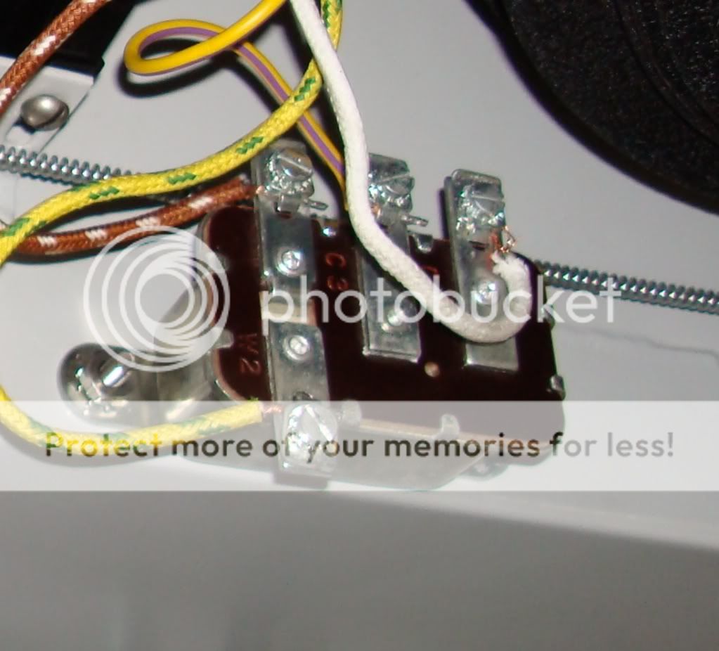
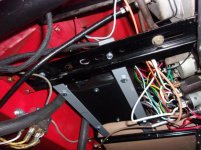
Here are photos showing the harness for my 1957 TR3. I laid them out to see how everything went together. One is the overall layout, the others are close-ups. You can see the wires for the OD dash switch. If you're asking how they were "run" behind the dash, it was "up and out of the way" from the relay, which is mounted on the lower left corner of the battery box (as seen from inside the car).


Thanks Keith that is kinda what I am looking for, the wire routing from the dash switch and where the dash switch meets the harness after relay. I wanted to see a picture of the original wire route, but it is starting to look like a rare bird. What I read from Don Elliot posts is he had made a sketch of his probably because cameras like today were not common when restored his car in 1989. He bought the car new in 1958 and it was probably no big deal to him.
I did find an old battery box that has one of those tie holder deals right behind the relay on the bottom of the battery box. I never knew what it was for, but know I think the tie held the wires on the bottom of battery box as the wires went away from the relay and back to the firewall to connect to the dash switch.
Just curious are the wires coming out of the OD dash switch gray?
thanks again --steve
Offline
Yes, Steve, the wires out of the OD dash switch are gray, no polarity. Attached is a photo of underneath the dash showing the relay and the wires out of it, which go to the gearbox top under the carpet and a grommeted hole on the left (driver's) side of the tunnel, with the others going up to the OD dash switch and the white and brown wires going to the ignition switch and the ammeter, IIRC. As my car is still with Macy's Garage, I can't check to see the routing, nor verify the presence or absence of clips for the wires.
You can also see where I've installed a new heater from T7 Designs in the UK. https://www.t7design.co.uk/products...w-lightweight-heater-with-side-vents-12v.html
.jpg")
You can also see where I've installed a new heater from T7 Designs in the UK. https://www.t7design.co.uk/products...w-lightweight-heater-with-side-vents-12v.html
Attachments
Thanks Keith for your reply. I purchased an od switch a while back and it had a gray wire, but I believed the wire was incorrect because it was gray, but now I think not, and it is a gray wirer. Plus, I am starting envision a way to run the switch using some of those clips like on the temp gauge that should work out and look kinda original. There a couple of nice original cars that come to the large local show here and the guys are pretty cool, and I think they will let me look up under the dash.
Those newer heaters look like they come in and out easier than the old ones—plus the older heaters are getting difficult to find.
Thanks steve
Those newer heaters look like they come in and out easier than the old ones—plus the older heaters are getting difficult to find.
Thanks steve