• Hi Guest!
    If you appreciate British Car Forum and our 25 years of supporting British car enthusiasts with technical and anicdotal information, collected from our thousands of great members, please support us with a low-cost subscription. You can become a supporting member for less than the dues of most car clubs.

    There are some perks with a member upgrade!
    **Upgrade Now**
    (PS: Subscribers don't see this gawd-aweful banner
Tips
Tips

Plan on rewiring a BJ7 with a new harness

bob hughes

Luke Skywalker
Country flag
Offline
Hi guys

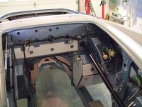
I have the engine out for a rebuild, and I am about to tidy up the engine bay - rip out the electrics and replace with new, the steering shaft and suspension etc. already removed, and I am getting ready to spray the engine bay. has any one any tips regarding the rewire. My only experience has been to renew the horn push and signal cable in the past, and it was relatively straight forward after I sorted out the colour scheme on the new cable which was nothing like that shown in the book. Will the new wiring loom give me similar problems?

:cheers:

Bob
 
Tips - go to a local photocopy shop and have them blow up the standard size wiring diagram to a really large size. Makes it easier to read and trace wiring routes

-take lots of pictures or the old wires and how they are routed, including what holes they pass through in the firewall before removing the old wiring

- instead of removing all the old wires from the back of the instrument panel at once (or any other component for that matter) cut the wires a couple of inches from their attachment point, leaving enough of the old wire attached to the component so you can tell the color pattern. Then replace the wires one by one from the wiring harness.
 
I agree, I have changed harness on My MG TD with Autosparks- very good quality (and historically correct loom)-No commercial interest
Cheers
 
Thanks guys all good stuff.

Good news about the harness colours, can't think what went wrong with the horn/indicator harness.

I had the wiring diagram blown up to A1 years ago in anticipation, but eventually posted up the diagram and codes at A3 onto board on the wall of the garage. Photos already taken and I will take the advice on leaving the tails on the various switches.

Thanks again

:cheers:

Bob
 
Hi Bob, i agree with all the above. When I did mine one tip I got was that when starting, pull the harness thru the large central hole in the firewall first. It lays out pretty good from there. Make special note to all the straps and connections with close up pictures before you take it apart. My harness as well did not match the colour codes exactly. It was a combination of the later BJ7 & BJ8 with some coloured circuits from the early 100/6 drawing. After the harness was in place I rang out every circuit with a continuity tester and put small labels on the ends. Of course I had modifications because I eliminated the original 2 fuses and installed two fuse boxes inside the cockpit as well as going to an alternator. Good Luck. Dave.
 

Attachments

  • DSCF1978.JPG
    DSCF1978.JPG
    48.2 KB · Views: 136
Hi Bob,

The only things I'd add are to get hold of replacement park lamp rubber boots and any other grommets that may be missing. Also apply dielectric grease to all termination points and bullet connectors before assembly to keep corrosion at bay. It'd help to clean the areas where the loom will run as even a small amount of dirt transfers quickly from fingers to the cotton braid and it is near impossible to get it looking clean again.

Check how many double and single bullet connectors your loom comes with- mine was short about five single ones and had two doubles left over even after using doubles in place of the missing singles.

Andy.
 
As far as corrosion on connectors I use a product ccalled No OX. It is sold at electrical supply houses and is specifically created to stop corrosion on electrical junctions. I used it on my bugeye that I did a Concours restoration on and never had an electrical connection isuue in a 14 year time span. Use sparingly and wipe any excess off as it is like never sieze. It multiples once out of the bottle :smile: Just use small amounts on the connection
 
All good stuff, thanks chaps.

My harness has now arrived and I am amazed at how much material there is on the cockpit side of the bulkhead. There must be nearly 2 feet beyond the bulkhead before it splits into the three legs for various instruments and switches on the dash. I have checked out the engine bay side ( easily done) and now I am working on the cockpit side, checking wire by wire. Just one point here, can the cockpit side be installed with the heater in place?. My car has not been stripped right down so life is going to be a little difficult!.

Just got my head under the dash to examine the old harness and can see why the harness is the length it is. I did not fully realize the extent of the area behind the dash.

:cheers:

Bob
 
Last edited:
Yes it fits through ok, you just have to make a tight turn inside right after the big grommet. Might pay to bind the looser wires together with something like teflon plumbers tape. Teflon tape is really slippery and ideal for pushing braided wire ends through rubber grommets and park light boots as well as pushing the steering column loom down the stator tube in one go. Andy.
 
Thanks Andy, sounds like a good idea, I'll give it a try when I get to it. Any tips for terminating the wires behind the dash - remove instruments and wire through the hole? etc.

:cheers:

Bob
 
Ho Bob,

No problem. I had the dash panel off to wire most of the items, just as easy to remove the switches to wire them. The BN4 wiring has braid over each wire so stripping the ends cleanly is near impossible. I used a razor blade to cut through the braid cleanly then regular wire strippers to cut the PVC insulation inside it. Not sure if your car has braided wires, perhaps you just have the PVC which will make it simpler.

One problem I had was that I pulled the bulk of the harness on the wrong side of the oil pipe or something and only found out when the last switch wouldn't quite reach. From memory there are three loom branches behind the instruments and it'd pay to photograph or draw their route first since they really need to go back the same orientation.

Depending on the source of your loom you may find the instrument lamp holders are junk. Mine were and the original ones were in average to poor state too so I had to scrounge up some good original ones and fit them. Check how each one fits in its socket, if they fall out immediately or only just stay clipped in or completely won't go in then they may have come from the same place as mine. I found some original solder-on wire terminals for the bulb holders as the new ones were crimp on, you could perhaps reuse the crimp ones by drilling a small hole down the middle and soldering them.

Although it might look complicated when looking at the mass of wires in a plastic bag, once you get the loom routed into place the rest is very simple.

Andy.
 
Thnks Andy

I have already done the big thing and sliced through the harness at the bulkhead so the die is now cast. I can see what you mean about the three way split and have already had a look at the instuement lighting to see what could be ahead. Still sanding down the engine bay at the moment and getting ready for the paint. Hopefully next week, the engine could be back with me in the next fortnight.

:cheers:

Bob
 
Back
Top