• Hey Guest!
    British Car Forum has been supporting enthusiasts for over 25 years by providing a great place to share our love for British cars. You can support our efforts by upgrading your membership for less than the dues of most car clubs. There are some perks with a member upgrade!

    **Upgrade Now**
    (PS: Upgraded members don't see this banner, nor will you see the Google ads that appear on the site.)
Tips
Tips

Pics of engine. Help with next step -- valve adju

2wrench

Luke Skywalker
Country flag
Offline
Business first: '74 TR6. Rebuild. First valve adjustment.

Number 1 piston top dead center.

Adjust valves 1 -12, beginning with valve 1, to .010.

Is this the correct procedure? Suggestions or whatever
appreciated. Also, please verify the .010. Thanks.

Now pictures because I'm happy to have my head on along
with the rocker assembly.

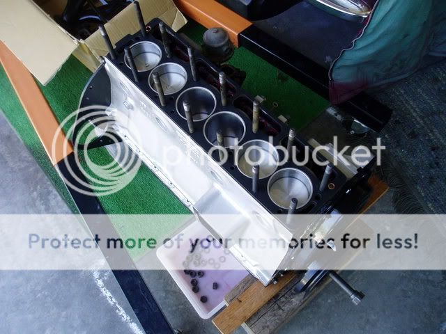
First, finally, finally the block with gasket in place
ready to receive the head:

P1010001-37-1.jpg


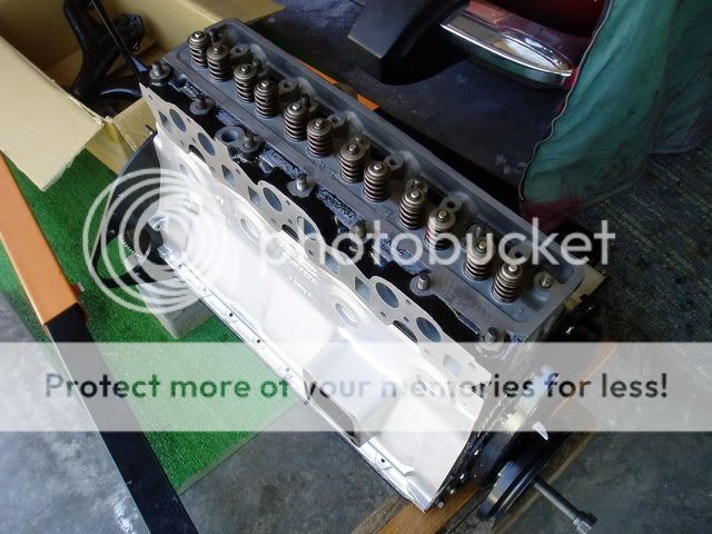
Head placed on block but not bolted on yet:

P1010002-35.jpg


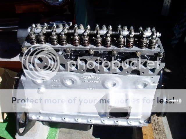
Head torqued to 80 lbs.; rocker assembly placed and
torqued to spec, forget the number for sure, but
maybe, like, 34 or 36 pounds or something:

P1010015-20.jpg


Engine fell off its blocks during head torqueing sequence
and was lifted via chain to be reset:

P1010003-33-1.jpg


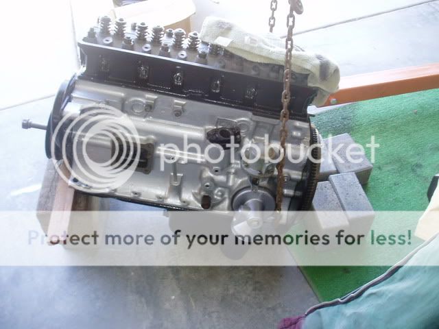
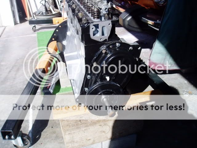
Lastly: My timing chain cover bolts are not painted. Do
you think I ought to touch 'em up black?

P1010016-18.jpg
 
I can't say anything about the specs you need, however personally I like having the hardware not painted.
 
2wrench:
I also prefer to leave hardware unpainted. Use galvanized hardware, or stainless if you are rich, where exposed because the regular stuff will rust and get ugly. Your motor looks great. The valve lash depends on the cam being used. If it is the stock cam, refer to your shop manual. If not, get the cam specs from the cam provider. You should have the shop manual of your choice by your side as you assemble. You will have to refer to it often.
 
I'm using stainless on the exposed bolts and nuts, but would have painted them to prevent rust showing up on the nice paint.
 
Here are some spec numbers and installation
instructions. I thought about posting this to the
thread "Graduated, my cam has been degreed," as it
explains a whole lot of confusion therein:

BP270
-
TIMING VL/VC FL LTDC
HR270/2 INLET 22 - 70 .415"/.012" 112 .039
EXHAUST 62 - 28 .400"/.014" 106 .045
Latest design asymmetrical profile using short duration opening, long duration closing inlet with
long duration opening, short duration closing exhaust. Straightforward installation - no
machining required. Standard valve springs may be used. Up to 10 BHP can be gained with
excellent bottom end and mid range power.

INSTALLATION
To set your cam timing, you will need a 360 degree protractor and dial indicator. The engine
must be set to TDC and the protractor bolted to the crank pulley. Attach the dial indicator so that
the foot is resting on valve spring cap (or follower) Attach a pointer to engine and zero
protractor. Engine is now at top dead center with protractor reading zero.
Turn cam shaft until full lift is shown on the #1 intake valve. Then turn crank-shaft to 112
degrees ATDC. Next, without moving crankshaft or camshaft, install chain on crank sprocket
and line up the two closest holes on your cam sprocket.
NOTE
VL - Valve Lift
VC - Valve Clearance
FL - Full lift shown as degrees after TDC for inlet before TDC for exhaust.
LTDC - Lift at TDC

So here is what I've got. Might just as well be written
in Greek. Can anybody help me decipher the hyroglyphics
and more simply state how to adjust my valves, after
rebuild? Help appreciated.
 
Notwithstanding the cam specs, I went ahead and set
the valves per the Bently manual specs, differently
than a friend had told me, when you read the procedure.

I appreciate why not a lot of responses on the question.
It gets rather wordy. I'll be double-checking with
my vendor tommorrow and seeing if anything should
change.

Best to ya,
 
My BPNW TH5 Cam valve settings are .014" Intake and .018" exhaust, so we're close.
 
Thanks, Paul. Yeah, the darned instructions tell you
to open two valves by number; adjust to .010 on another
named two; then working your way along opening two
and adjusting two untill all twelve are done.

So, did the exercise. If my specs must change cause
I bumped the cam a bit, I'll be posting to share.
Thanks for sharing, though I do think your cam is rather
radical....can you see me a little green???....

But, that said, I didn't want an overly radical cam, just
a few more horses, so that's what I got. It could be so
mild that the original specs might still work. We'll
see. Maybe down the road, when I grow up and the dust
settles, my wife will allow me to build a real screamer
like you.
 
Mine isn't overly radical. I wanted a nice cam for street use with the power between 2000-5500 and I think that I got it. The duration at 290 is a little longer than most, but the lift isn't as dramatic, which can lessen wear on the valve train.

There are two ways of getting more air/fuel in and out the engine. One is higher lift and two is longer duration or opening of the valves. The more radical that you go on each gives the torque curves for racing and really loppy idles.
 
Sorry for calling it that, Paul. I just thought
150 hp target is rather high reaching. Evidently,
other parts come into play....but I was giving a good
amount of credit to a hot cam. Let's you know just
how much I don't know. But I'm hear trying to learn.
 
Not a problem. I learn a lot here every day. When I stop learning, I'm going to get scared, because I'll either know too much that I shouldn't or it's all over.....
 
Just be sure that the lash setting is the same for both the intake and exhaust. I have the GP2 cam and the lash setting is different for the intake and exhaust. However, the procedure is the same. This adjustment is not to be guessed at. The cam card should have the lash setting info on it.
 
2W,

Do you have the instructions that came with the Cam? I would call the seller and confirm the valve lash before you set both at .010", just to be sure.
 
Right, gentlemen. The info I seek is right before me.
Intake at .012; exhaust at .014. I am on such a steep
learning curve that I did not recognize this as the
information to glean. It is right on the cam specs
that I posted above. Just kind of in the maze of numbers
such that I could not appreciate.

Having culled that info out by contacting bpnorthwest, I will proceed to set the valves per spec for my cam.

I am now a bit shy for posting procedures and pics at
the expense of appearing a bufoon. I will likely do
this, nonetheless, because I believe there are others
out there with less the engine acumen who may find
a nugget in my display of ignorance, which is why I
joined this Forum, because I truly believed that ignorance
would be tolerated. Please be patient with me and know
my whole thing is to learn and share for the benefit of
all, especially those of us who have yet to appreciate
the difference between an exhaust port or an intake port.

I remain,
Sincerely Yours,
 
2W,
I'm a certifiable bufoon, so I'm always appreciative when these types of questions get asked. So fear not, because there are plenty of us out here! :thumbsup:
 
Re: Pics of engine. Help with next step -- valve

Dennis, your posts are a treasure.

We've been away, playin' out over the weekend and so didn't see too much of the BCF or I'd have jumped in with the .012"~/.014" spec out of that "pile".

Don't you DARE back off of posting. Your endeavor at this should be an inspiration to MANY who'd ordinarily just run away from a task like this rebuild! You're PROVING these old lumps ain't "rocket science" and are both understandable and RENEWABLE by someone with a willingness to dive in and LEARN!

I, for one, laud your attitude. I've a neighbor who determined she was going to learn to do the same thing with a Fiat 124 Spider twin-cam 2L. She did the task with my guidance on the floor of her garage over a period of a few months. She even got "Weber DGV 101" on one of her kids' old school desks there. She was like a little kid when it lit on the first turn of the key... She's still amazed when she turns the key and the thing lights off. There's a sense of accomplishment NO amount of money spent to have someone else do it would replace. You're intrepid, lad. We want to see MORE like you. :thumbsup:
 
Re: Pics of engine. Help with next step -- valve

If I see your posts start to disappear, I'm going to send the all of the CA guys to hunt you down.

Remember, the only "dumb" question is the one that is never asked.

And I can't count the mistakes I've made even when I've asked twice, so don't ever feel bad.

Notice that I missed the .012" / .014" spec in your previous post?? Duhhhhh, Paul!! It's the same as your cam!!!
 
Re: Pics of engine. Help with next step -- valve

:lol:


"We're ALL in this together."
 
Re: Pics of engine. Help with next step -- valve

lol, and you think you're a buffoon. i haven't even started putting my engine together. it's sitting in the corner of my diningroom. haven't started cause i don't have a place to put it in the car and cause i'm a bit afraid of screwing it up. and it needs paint...
 
Back
Top