• Hey Guest!
    British Car Forum has been supporting enthusiasts for over 25 years by providing a great place to share our love for British cars. You can support our efforts by upgrading your membership for less than the dues of most car clubs. There are some perks with a member upgrade!

    **Upgrade Now**
    (PS: Upgraded members don't see this banner, nor will you see the Google ads that appear on the site.)
Tips
Tips

TR2/3/3A Panel Rheostat

BobbyO

Jedi Hopeful
Country flag
Offline
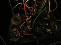
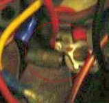
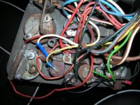
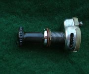
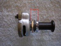
I think I have wired my post TR60,000 car in accordance with the appropriate electrical system wiring diagram and am now attempting to get things to work. From reading older posts I suspect I am short a few ground wires (speedo and tach) that would account for some panel lights not working but not all. I am questioning the panel rheostat I have installed. MM has two different part numbers for the panel rheostat and the heater rheostat. I have several rheostats and would like to know how/if you can tell the difference between the two and if I have a heater rheostat in the place of the panel rheostat would it make a difference?

Also, in an older post, Randall said the in-line fuse was there primarily to protect the tail lights. I'm wondering about this because, now my tail lights come on whenever power is applied to the car, with the light switch in the off position. No switches on. Would anyone care to provide a guess as to how this is happening?????

Thanks for any input.
 
If you turn up the panel reostat with a short, it will fry the reostat. It's easy to check with a simple voltmeter, though, to see if it is still putting out power, or dead.

This is the heater reostat..on the right of the pic, with no guts in it. When it was new, it was made of a white porcelain.


This is a shot of the panel reostat...the one with the orange wires going into it. It is smaller, and usually made of black bakelight material.
 
Thanks John. I have 5 different rheostats but they are all the same size and none with black bakelight material. I know at least one is a heater rheostat because the knob attached with a screw, not the push button spring clip most knobs use. Probably an early heater rheostat. The backing of all of these rheostats seems to be a ceramic material pretty much like the one in your panel rheostat picture. And, most likely when they were new, were white. Do you have any measurements? Can a heater rheostat be used for the panel lights?
 
The panel rheostat is rated at 5 or 6 ohms, while the heater rheostat is only 2.5 ohms (at maximum resistance but not off obviously). The panel lights will still work if you use a heater rheostat there; they just won't get very dim before going out completely. Given how dim the panel lights are anyway, I can't see that as a big problem. (In fact, my early cars have only a switch and I've never felt that a rheostat would add any advantage at all.)

I'm less certain about using a panel rheostat for the fan control, but I think most likely it would be OK. There is a possibility the control could overheat and burn out but I think not (based in part on my experiments long ago with rewinding the motor to turn faster). Half the range or so will be useless, but again most of it is useless anyway IMO. Even back when I used a heater, a simple switch would have done just as well. I always wanted either more heat than it could deliver on high; or none at all.

The tail light issue has to be a miswiring, probably under the dash. Easy first test is to remove the in-line fuse. If the lights go out, then either the other side of the fuse is not connected to S1 on the switch, the switch is defective, or something else is connected to S1 that is supplying power to it. (I assume you realize the switch has 3 positions and you have to rotate the knob to turn it full off.) Since you seem uncertain about the diagram you used, a pointer to it might be helpful.

In John's photo above, the panel control is in the foreground with the bundle of red wires attached to it. The black bakelite thing is the head/tail light switch.

Oh yeah, the diagrams don't show the ground wire for the speedo and tach, but it is usually needed. Black (obviously), attached to the tie point on the back on the panel, then has ring terminals to go under one of the mounting nuts on both tach and speedo. The original ring terminals were very wide for some reason, but ordinary modern ones would work just fine. I also advocate adding a ground wire for the fuel gauge, which could be part of the same wire if you want. The original design relied on the ground through the mounting clamp, which just isn't very secure and often leads to problems in my experience.
 
Randall thanks for the information. I'll use a heater rheostat for the panel lights since I have so many of those. I also have one of the single off/on panel light switches but read it would not be feasible to use that since the mounting hole is a different size.

Is there any way to test the head/tail light switch to determine it is truly off in the off position. I thought that was a possibility but couldn't see how to determine it was actually off. I was working on this problem yesterday and, as I remember, when power was applied the tail lights came on without any other switches on. I could be wrong. Just now I had to turn the ignition on for the tail lights to come on without any other switches on. I removed the fuse and the tail lights stayed on. Nothing else is connected to S1. I have the dash out, hanging by wires, the water temp line and the choke cable. Attached a picture but it's so dark and such a rats nest I doubt it's useful. Light and flash didn't help.

The wiring diagram I'm using came from "Practical Hints for the Maintenance of the T.R.3", sixth edition. It's the one with the rear parking lights.
attachment.php
 

Attachments

  • DSCN1476.jpg
    DSCN1476.jpg
    38.9 KB · Views: 224
I tested the head/tail light switch by checking for continuity between A and S1 with the switch in the off position. There was no continuity so the switch is not shorted internally.
 
The switch isn't likely to be the problem anyway, since they still come on with the fuse pulled.

Looking at your photo, I'm wondering if perhaps the white connection to the generator warning light isn't touching the terminal on the rheostat. They seem awfully close together. Might be that if you just turned the bulb holder the other way, the problem would disappear.

Also, I assume that red wire at the wiper switch isn't actually going to the wiper switch. Hard to tell where it does go, though.
 
Randall, sorry for the poor picture. Although very close none of the wires are touching. The red wire is actually the other end of the fuse holder and goes to the panel rheostat. The fuse holder wiring starts out RG as it should but changes to red at that end of the holder. I'll re-position wires and see if I can get a better picture. Thanks for the help.
 
Must be just the angle, then.
attachment.php
 

Attachments

  • DSCN1476_zoom.jpg
    DSCN1476_zoom.jpg
    55.1 KB · Views: 200
Was the angle. That red wire goes to the lights in the speedo and tach and is lower than the generator light post. Didn't have red/white wire as called for. I'm giving up for the day. After awhile you forget what you've checked and what you haven't. Been chasing this problem for several hours with no results, actually things have gotten worse. Now nothing works, not even the horn and, somehow I've got power on the ground wire at the control box. Have no idea how that is happening. I've attached what I hope is a better picture if you want to take a look. Have power on A, A1, and both ends of both fuses yet nothing works. Go figure.
attachment.php
 

Attachments

  • DSCN1478.jpg
    DSCN1478.jpg
    86.4 KB · Views: 247
somehow I've got power on the ground wire at the control box. Have no idea how that is happening.
That shouldn't be too hard to chase down, and I'd do that next. Bad grounds cause all sorts of strange symptoms.

I believe there should be two wires on the 'E' terminal, one of them should be tied to the body nearby. Check that tie point (on my car it is screwed through the edge of the battery box). If it's grounded, then the wire to the E terminal is broken or not making good contact. If you find 12v there too, then the battery ground strap isn't making good contact to the body. Actually a common problem if the body has been recently repainted, as paint doesn't conduct. A big 'star' type lock washer between the ground strap and the body will help make sure it makes good contact (the points of the star cut through the paint).
 
The wires look pretty nice to me considering all that gets stuffed in that tight spot. I recently put a new wiring harness in a 61 tr3 with the rheostat and I remember dealing with a spot for 3 wires on that rheostat; it was painful. I had problem with dash lights somewhere where they hooked into the headlight switch for power. Moreover, I think the problem I had was I was putting the tail lights on the wrong peg of the light switch; the tail lights needed to be on at both pulls of the switch, parking and headlights. I did add a fuse for the tail lights circuit. I hope that helps. I am curious what is that metal cylinder by the oil gauge?
 
I am curious what is that metal cylinder by the oil gauge?
That's the original in-line fuse holder. Normally it would be clipped to the bottom edge of the larger dash panel when the instrument panel is installed.
 
So there was a fuse on the headlights or taillights Randall? And if so that stock fuse/fuse holder goes to headlights or tail lights then kinda disappears at the ignition light? The wiper switch is at the bottom center of the panel in the picture, right. Just curious again the car is still positive ground, right.
 
The in-line fuse was for the taillights, supposedly because people were getting the rear lamps crushed and having electrical fires. But it also feeds the panel lights. According to Bill Piggott, it was added at TS38177 (although he says there was a second fuse for the brake lights, which I don't believe is correct).

Hard to see in the photo above, but the disappearing end goes to the panel rheostat, which doubles as a tie point. The 3 other red wires going to the same terminal supply power to the front marker (aka side) lights and the tail lights. Not the way I would have done it, but probably cheaper and easier than messing with a bunch of bullets and sleeves.

Yup, that's the wiper switch at the bottom of the photo (which would be the top when the panel is installed). On these later cars, the wiper switch actually grounds the motor to make it run (so the motor can park with the switch off, by grounding itself).

Looks like the ammeter is wired for negative ground; but that's the only difference under the dash. Everything else remains the same except the battery connections of course, and perhaps the ignition coil.
 
I want to thank everyone for all the help. Randall is right, I have the car set up for negative ground. And, as I stated the other day, I had been chasing the problem for numerous hours and was obviously tired and was connecting my meter wrong to read voltage on the grounds. Yesterday I removed most grounds then reconnected them and am back to where I was, now the horn works, and the head/tail lights work. I still have other problems to solve but will tackle them later. Will be out of town for the next couple of days and will attempt to tackle them when I return. I'm retired so I can spend any amount of time on this as I want. It's good but often frustrating. Thanks again.
 
Re. the rheostats: As Randall stated, the heater rheostat as a panel rheostat is OK, but the panel as a heater will cause significant overheating at slow motor speeds. Along with having different electrical values they are slightly physically different (not counting the knob) See attached
Everything appears to be correctly connected in your latest photo. After you correct the power at a ground problem (scary) you should have 12v at the A connector on the light switch. It's the other end of the A1 connector wire on the control box . (#36 wire, brown w/blue) That 36 wire continues on from the light to the ignition switch. That A connector at the light gets lose and/or corroded & might explain your open circuit. The light switch has been know to fail but in the opposite. (The dash & tail lights never turn off!)


Attachments

  • 2012 heater sw_2.jpg
    2012 heater sw_2.jpg
    49.5 KB · Views: 120
  • Panel Rheostat_2.jpg
    Panel Rheostat_2.jpg
    62.5 KB · Views: 125
Thanks for the pictures. When people were saying the panel rheostat was smaller, I was thinking size of the rheostat itself (the wired portion) not shaft length. Seeing the shorter shaft length, I do have a panel rheostat but a heater rheostat is already installed and I'm not going to change it now. Am now working on the turn signals, trying to solve one problem at a time. Dash lights will be next but I think they are in good shape. Always optimistic.
 
Back
Top