• Hey Guest!
    British Car Forum has been supporting enthusiasts for over 25 years by providing a great place to share our love for British cars. You can support our efforts by upgrading your membership for less than the dues of most car clubs. There are some perks with a member upgrade!

    **Upgrade Now**
    (PS: Upgraded members don't see this banner, nor will you see the Google ads that appear on the site.)
Tips
Tips

Over Drive is Back Together

Tinkerman

Darth Vader
Offline
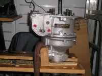
After dissasembly and cleaning, waiting for parts, a number of phone calls, waiting for more parts, reading and re-reading the manuals and the articles, I am happy to say that it is all back together, no parts laying on the bench, and everything moves freely. It is now ready for the tranny. The tranny has been patiently waiting for the OD to be finished because I had to use the main shaft in the assembly of the OD. Now it's back to the tranny, join them up and on to the testing. Yea! Another step forward.

Cheers, Tinkerman
 

Attachments

  • 13678.jpg
    13678.jpg
    106.3 KB · Views: 273
Congrats!

Yur a better man than me Gunga Din
I wouldnt attempt it...


let us know how it works out
 
On the overdrive we re-built, my neighbour set it up on his lathe with a sheetmetal plate to cover half the open end and the lathe drove the input shaft at a speed where we could manually pull on the lever to hear it change speed. This indicated that it was working. Also the pressure gauge we fabricated rose to 325 psi, so we know we were good.

Others have reported that they use a huge drill to drive it with enough force and speed to achieve this. But we didn't have such a big drill. Herman (HVDA) told me he has used the drill method.

The sheetmetal plate kept all the oil in the overdrive even with it only half closing the open end.
 
Looks good Tink...great job.
 
I hope to be at that stage this winter. I have an eBay TR6 box with A-type OD all in pieces in the basement. The problem I'm having is the thought of hefting a heavy gearbox that is functioning well out through the car; did it back in the day and it was a PITA.
 
Is there supposed to be a "Grasshog" sticking out the middle - I don't remember that from the manual - performance mod perhaps?;) Cool.
 
Don't forget that there is a spacer that goes between the operating lever and the seal. The lever is also supposed to be installed so it puts some pressure on the seal.

And don't pull my favorite stunt, leaving out the pump cam!
 
Don Elliott said:
Others have reported that they use a huge drill to drive it with enough force and speed to achieve this.
It actually doesn't take much force at all; and if the seals are in good shape, not much speed either. I used a 1/2" drill motor because that was what I had handy, but I daresay the old 3/8" B&D would have still built the pressure.
 
Thats exciting, real progress. Quite a way to go yet for me but been wondering about these springs, they're all different. Go with em?
 

Attachments

  • 13682.jpg
    13682.jpg
    82.8 KB · Views: 212
"Is there supposed to be a "Grasshog" sticking out the middle - I don't remember that from the manual - performance mod perhaps?;) Cool."
Rob, its called multi-tasking, heh.


"Don't forget that there is a spacer that goes between the operating lever and the seal. The lever is also supposed to be installed so it puts some pressure on the seal."

"And don't pull my favorite stunt, leaving out the pump cam!"

Got it covered Randall, I'm waiting to install the solenoid. The cam is actually sitting in position in the overdrive waiting for the tranny.

Thanks for the comments, Tinkerman
 
Tinkerman,

If you alternate the shorter ones and the longer ones, the different lengths shouldn't matter.

IMO

Well done.

Steve Spangler
71 Spitfire MKIV

now in it's 25th year of ownership
 
I have mine apart at the moment and they are actually 4 short ones and 4 longer ones. Check the re-assembly docs that are available for correct positioning.
 
TRDejaVu said:
I have mine apart at the moment and they are actually 4 short ones and 4 longer ones. Check the re-assembly docs that are available for correct positioning.

Thanks, yes I see that. One of the short ones is longer and one of the long ones is longer. I wondered if spending the money on a new set for uniformity would make a difference or no big deal.
 
Sail, I just looked at your springs and really don't think you have a problem. As you probably know the long ones go on the outside pegs and the shorter ones go on the inside pegs. Their main purpose in life is to keep the cone clutch held against the annulus. I suspect those minor variations wont affect theire operation. In fact I'm betting on it because mine looked about the same as yours. I'll know after I put on the test bench.

Cheers, Tinkerman
 
Thanks Tinkerman. I'll bet with you and stick with them. Anxious to hear about your test...good luck.
 
sail said:
Thats exciting, real progress. Quite a way to go yet for me but been wondering about these springs, they're all different. Go with em?
Most likely they are fine, but I would compare the free lengths to those given in Nelson's article . If yours are significantly shorter, I'd replace them.

Not because of the variation in length, but because a shorter free length means they have taken a 'set' and will not exert as much force as they should.
 
Thanks for that I went out and measured and they look like they will be the least of my problems.
 
Yep measured mine also Randall, early on and they were within tolerance. His article is very prominant on my work bench.

Tinkerman
 
Back
Top