• Hi Guest!
    If you appreciate British Car Forum and our 25 years of supporting British car enthusiasts with technical and anicdotal information, collected from our thousands of great members, please support us with a low-cost subscription. You can become a supporting member for less than the dues of most car clubs.

    There are some perks with a member upgrade!
    **Upgrade Now**
    (PS: Subscribers don't see this gawd-aweful banner
Tips
Tips

OD control

Country flag
Offline
After reading stuff on another forum I have concluded my overdrive control ain't working. I've checked all my books and they just tell me how to check that it ain't working. I opened it and cleaned it (its simple inside)and it still ain't working.
I've tested the opening and closing of points and all but when I turn off the OD with the ignition still on the light is suppose to stay on until I move the throttle a number of degrees. But the light goes out immediatly. (This means the only control I have is with the dash switch and throttle does nothing.)
What am I missing? Could the control box wires be switched by the PO (many years ago)?
 
Not sure what "light" you are referring to.
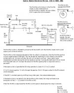
Attached is a partial schematic & explanation of the OD controls.

The most likely problem is that the "throttle switch" is not properly adjusted or it might be incorrectly wired.

The throttle switch can be adjusted by loosening the arm clamp & rotating the shaft of the switch.

Remove the wires on the switch & measure continuity between the two terminals.

The attachment shows the correct switch adjustment & the incorrect adjustment.

Check the switch adjustment & the wiring.
D
 

Attachments

  • 12296.jpg
    12296.jpg
    119.5 KB · Views: 212
Thank you, Dave.
In all the books it suggests a 12 volt light be attached to the upper terminmal and ground. Turning the ignition and over drive on would turn the light on and when the OD was switched off it would stay lite until the throttle was moved. Thats what didn't happen.
The only adjustment it the slot in the lever. Mine is set at verticle and aligned with the flat part of the cam when at rest. Correct???

White with green to top or bottom terminal or does it matter?
 
On my diagram, terminal one is the upper & should have the white/violet wire. It would work either way but would affect where you connected the test light. The test light should be between the W/V wire & ground.

Since the light is going out immediately, there is no connection between the W/G wire & the W/V wire when the throttle is closed. Or there is no connection between C1 & C2 contact on the OD relay itself.

I urge you to actually remove the two wires from the throttle switch & measure continuity across the contacts while you operate the switch.

Your description of near vertical slot & aligned with the flat part of the cam should be close.

Check all wiring on the OD relay & the throttle switch for correctness. Who knows what the previous owner may have done. The OD will actually work with both the OD relay & the throttle switch missing, just not as originally intended.

Actually things will work fine just as they are if you just remember to apply a little throttle pressure when shifting out of OD.
D
 
Dave, on your diagram the shaft slot is purpendicular to the flat spot on the cam. I thought it was aligned when I opened the unit. Regardless the flat part should be verticle when at rest, right? Everythihng else seems as it should be except the wires were switched. I'll give it a test run tomorrow. I know I'm missing something simple.
 
Hi Rich,
Here is the way I set my throttle switch up. I connected an ohm meter to the two contacts on the switch, then had a helper sit in the driver's seat and push about 20% down on the accel pedal. With the ignition OFF, I loosened the nut on the throttle switch arm and turned the switch shaft until the multimeter just changed to zero ohms (give or take an ohm or two). Tighten the nut back up and take it for a test run.

IIRC the throttle switch rotates 80 degrees between foot off pedal, and to the floor. So you're looking for a 16 degree rotation (throttle switch) to get 20% throttle. I'll see if I can dig up the notes I made on that tomorrow if you need them.
 
TH,
The slot in the shaft would normally be nearly perpendicular (90 degrees) to the flat spot on the inside cam, slot vertical as viewed from the LH side of the switch. I say nearly because the slot usually ends up being slightly CCW from vertical.

Contacts closed with the throttle at rest, contacts open when the throttle is slightly depressed & beyond.

Unless you happened to have one of the rare "replacement" switches which may have the slot machined parallel to the flat spot on the cam, doubtful.

Greg, do you have the position backward in the above description or am I reading it wrong? With the throttle depressed 20% and more, the switch should change from zero ohms to open circuit. It should change from open circuit back to closed as the throttle is released.
D
 
Hi Dave,
Very well could be I got it back wards, been several years since I did it. Still, that is the transition point that I used. :blush:
 
Dave, the only thing I can come up with from your diagram is that C1 and C2 are stuck closed. Everything else seems OK. How can I test and can it be fixeds or is it a replacement thing of the whole relay?
 
Hi Rich,
If the C1-C2 contact were stuck closed the OD would be operated all of the time, regardless of the dash switch position.

The OD relay can be checked as follows:
1- Disconnect all wires from the relay
2- An ohmeter connected between relay terminals W1 & W2 should read about 70 ohms
If it reads much higher or lower, the relay coil is defective
3- The relay contact between C1 & C2 should read very high resistance
4- If 12 volts is applied to the relay terminals W1 & W2, the contact between C1 & C2 should read very low resistance.
5- The resistance between C1 & C2 should go back to very high when the 12 volts is removed from W1 & W2.

If you wish, the metal can may be removed from the OD relay to inspect.

We don't seem to be communicating very well on how the circuit is supposed to operate. I think that all of the necessary information is in the diagram & description that I supplied. These problems are often difficult to diagnose by mail. I don't know what else to offer.
Regards,
Dave
Ps - You need to use a good ohmeter, not a test light.
 
Thank you, Dave. The light was only used because all the books said to use it to test the throttle control. (I had to make one.) I do have an assortment of ohmeters and will try it tomorrow. I wasn't sure of the ohm values to look for so thank you again for that.
Rich
 
Well, finally success! It was the over-drive relay. The PO had connected it completly wrong. The interesting thing is that Dave's diagram and the one in Nock's book indicate W2 to earth while all the wireing diagrams in the books indicate W1 to earth. It doesn't make a difference but interesting.
This really does make a difference when moving out of OD. And less chance of damage to the drive train makes me very happy.
Thank you, Dave, for all your patience as I was getting frustrated.
 
Hi Rich,
Glad you got it sorted out. My original factory shop manual shows W2 connecting to earth & the original wiring harness is somewhat less scrambled with it connected that way.

As I said, diagnosing electrics by mail can be difficult. Especially with certain previous owners involved. "Inside joke". Glad you didn't give up!
D
 
Back
Top