• The Roadster Factory Recovery Fund - Friends, as you may have heard, The Roadster Factory, a respected British Car Parts business in PA, suffered a total loss in a fire on Christmas Day. Read about it, discuss or ask questions >> HERE. The Triumph Register of America is sponsoring a fund raiser to help TRF get back on their feet. If you can help, vist >> their GoFundMe page.
  • Hey there Guest!
    If you enjoy BCF and find our forum a useful resource, if you appreciate not having ads pop up all over the place and you want to ensure we can stay online - Please consider supporting with an "optional" low-cost annual subscription.
    **Upgrade Now**
    (PS: Subscribers don't see this UGLY banner)
Tips
Tips

General Tech O/D Electrical Wire Burned

OP
KVH

KVH

Darth Vader
Country flag
Offline
I'm pretty sure I'm unique. There's just no one like me around here.

I just cross-wired my overdrive wiring "under the dash" leading from the transmission to the column switch on the steering wheel. These are the wires that come from the switches mounted on the transmission cover of my TR4A. Not sure how I managed to cross wire under the dash where they meet the O/D column switch, but poor lighting is my excuse.

So, yes, I fried the yellow wire badly. The burn goes all they way back to the transmission switch--the most forward of the two switches. Or within an inch. I'll remove the O/D harness and rebuilt it, but for those here who may know, what might I first do to verify that I didn't also ruin the switches on the transmission cover or the relay under the dash? I can say with comfort that none of the wires on the relay appear to have been hot, and the ones leading to the column switch also appear good.

I'm hoping someone will tell me that the mounted switches are bullet proof. If I do need to replace either of them, is that done without removing the cover? Dear Lord tell me it's so.

But far more important than anything else, and I'm trying my best to recall, I thought I remember someone here saying it doesn't matter which wire goes to which side of the switches on the transmission cover. I guess its a fallacy to assume that means you can cross-wire under the dash? Those are two entirely different concepts because as the wires come from the O/D switches under the dash and connect to the column switch we're dealing with different purposes and a host of different current and connections--right? Reversing on the spade connectors at a switch on the transmission cover is one thing, but reversing under the dash and changing all that is different. Can someone say it better?

Maybe a bright electrical guy out there can help shed light on my predicament. I'm glad my kids weren't nearby to see what happened (and to smell the burning wires)!!

Thanks all. KVH
 

DavidApp

Yoda
Gold
Country flag
Offline
The switches just provide a ground for the OD relay coil. Either one will complete the circuit. You could check them with a test light. One side of the switch should have a black wire that is connected to ground the other side is the yellow wire. Disconnect the yellow wires from the switches then with a test light connected to power touch the test probe to the terminal the yellow wire was connected to. Then put the car in gear (second, third or top)and the light should light. If it does the switches are good. Check the test light works by touching the OD case with the probe.

I have added fuses to both the supply wires to the OD. That probable saved me from burning up the OD solenoid. It kept blowing fuses because the pull in coil was not being switched to the hold coil.

David
 

Sarastro

Obi Wan
Silver
Country flag
Offline
Well, look at the bright side: you've trained our brain to recognize the smell of fried wiring. As a veteran electrogeek, I trained my brain that way a long time ago, and I get occasional refresher courses. Old cars are very good for that.

It sounds like somehow you got the yellow wire connected to a power source instead of to the OD switch. If I were in your place, I would just replace the burned wire and make sure that it is connected correctly to the switch. I doubt that you have damaged the switches--I'd assume that they were OK and go from there. If you find that they are not, you will have to take off the transmission cover to replace them.

Is the yellow wire OK leading to the lockout switches on the transmission? If it is burned, unfortunately it should also be replaced, and that will require removing the trans cover. If that wire is damaged and shorts to ground, it will turn on the OD in all gears, and that's really bad juju.
 
OP
KVH

KVH

Darth Vader
Country flag
Offline
The only wire badly Damaged is the yellow wire that leads to the most forward of the two lockout switches on the cover. However, the damage seems to stop about an inch before the switch, and I can just pull the spade off and replace the entire wire. There are no other exposed wires on that switch. When you say remove the “transmission cover,“ you mean the center fiberboard hump, correct? I don’t believe there’s any internal wiring that would require that I remove the aluminum top transmission cover itself.
 

DavidApp

Yoda
Gold
Country flag
Offline
I have a 5 amp fuse in the relay coil power supply and a 10 amp in the solenoid line.

David
OD wiring wit fuse s.jpg
Close up of Fuse block and relay.jpg
 
OP
KVH

KVH

Darth Vader
Country flag
Offline
Thanks for all the help. Both switches on the transmission checked out fine, no other wires were burned, and my O/D works great. Now on to my HS6 carb problems.
 

Geo Hahn

Yoda
Country flag
Offline
I added an 8 amp slow blow fuse to the (brown) power feed to the relay:

SF_Fig_1.jpg
SF_Fig_2.jpg


SF_Fig_3.jpg
.

The idea is that it will blow if the pull-in coil sticks as it draws (22?) amps only briefly, not long enough to blow the fuse in normal operation.

The inline fuse holder was modified to allow a simple no-cut addition to the connection.
 
OP
KVH

KVH

Darth Vader
Country flag
Offline
I spoke too soon about my overdrive working. It was working shortly after I replace the burned wire, but not now. Something in the electrical is preventing my overdrive from activating. I hear nothing when I activate the column switch but a click at the relay when I deactivate. I see no bump in the ammeter gauge either way. In short, no overdrive. Is it likely a solenoid problem? Any advice would be appreciated. When it comes to “electrics,” I’m next to helpless. Thank you.
 

Geo Hahn

Yoda
Country flag
Offline
A methodical approach should reveal the problem.

I'd start by seeing if there is 12V to the C1 relay terminal (may be a brown wire).

You can then jumper it to the Yellow/Purple wire removed from the C2 relay and listen if that triggers the solenoid (the big click).

That should narrow the problem down to either the relay or the solenoid.

If the solenoid clicks then you check the relay and its connections, starting with confirming W1 gets 12V when the OD switch is on. If yes then put a ground on W2 and see if the relay clicks.

If it does then check that there is a path to ground for the W2 wire (Yellow/Green) when 2, 3 or 4 are selected and not when they are not.

One way yo do this would be to simply remove all wires from the relay and connect extensions to each (labelled) so you could experiment in comfort and not have to limbo under the dash. A spare relay could be used for testing and once everything is working then verify the original relay.

PS - I cannot account for why you do not hear the relay engage but do hear it disengage. If anything I would expect the opposite to occur.
 
OP
KVH

KVH

Darth Vader
Country flag
Offline
I found my problem. I soldered a bullet connector and did a horrible job—it just came right out, under the transmission cover of course and requiring my fifth interior removal in two months. Oh well, I keep learning. Some lessons are fun, but this one is another confidence shaker. Just how old am I now?
5AC50978-D8C9-493F-8B43-AB544845FD4C.jpeg
 
OP
KVH

KVH

Darth Vader
Country flag
Offline
In the pic above I should’ve shown the Moss bullet fitting and not just the sleeve. I realize that pic is a little confusing. All the actual bullet shows is a nice clean solder pocket in the rear out of which my wire apparently just pulled from the slightest tug.

Just FYI that’s what I get for trying to copy a Youtube recommendation.

I should ssk how others here solder bullet connectors. I used flux and I seem to recall my solder being awfully “watery.” I also believe I failed to heat the wire sufficiently prior to the final step of inserting the wire into the heated bullet and solder.

(Anyway, I hear footsteps coming down the hall so I better run. I don’t need any of this getting around.)
 

Geo Hahn

Yoda
Country flag
Offline
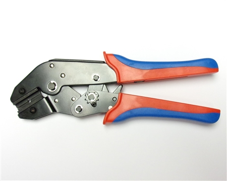
I usually use the usual bullet crimper (has to be used with crimpable bullets).

When I do solder these I strip and insert the wire (fluxed) so it is sticking out the end of the bullet, then apply the solder to the tip and the bit of wire showing. Helps to have scratched the end of the bullet to remove some of the plating. Once cooled I use the grinder to remove that excess that is sticking out of the tip.

Never had on come loose.
 
OP
KVH

KVH

Darth Vader
Country flag
Offline
Geo when you solder from the tip, does that draw the solder into the inner cavity of the bullet? Partly filling it? You don’t try to solder from the back end of the bullet?
 

Geo Hahn

Yoda
Country flag
Offline
I'm pretty sure the solder will wick into the bullet when everything is hot enough (sort of like sweating copper pipe if you have ever done that).

Let me know if you want to borrow my crimper.
 

Sarastro

Obi Wan
Silver
Country flag
Offline
The greatest problem in soldering is insufficient heat. Both pieces--the wire and connector--have to get hot enough for the solder to flow over them. First, your iron should be large enough, but not so large that you fry everything. I use a 25-watt one for this kind of thing. Put a little solder on the tip, so it acts as a heat transfer medium, and put the tip on the work. Then apply the solder to the inside of the connector, between the wire and connector body. When it's hot enough you'll see the solder flow nicely over the connector and the wire. It seems clear from your photo that the solder surrounded the wire, but didn't really flow over it as it should.

Another common problem is trying to solder parts that are oxidized or tarnished. They must be cleaned to bright metal. But you're using new parts, so that should not be a problem.

It's not strictly necessary to use flux, as long as the solder has a flux core. But a little extra flux helps a lot, especially if the metals are not perfectly clean (and it can be hard to clean older parts). I assume you are using a rosin flux; never use any acidic flux.
 
OP
KVH

KVH

Darth Vader
Country flag
Offline
I’ll be careful to follow that advice next time. One question I have, however, is that if I hold the bullet connector either in a vice or other device, it is standing upright and the solder seems to flow through and disappear through the little hole at the end of the bullet connector. Does this really mean that I need to hold that bullet connector sideways as I heat it up and solder it? That gets a little tricky, and makes me feel like I would need four hands.

Also, I went into my Moss catalog and saw a reference to crimp bullet connectors being only for certain, but not all, electrical components. Is that the case or could I use crimp bullet connectors on anything I choose in the car?
 

Sarastro

Obi Wan
Silver
Country flag
Offline
Yes, I forgot to tell you, effective soldering requires a minimum of three hands, and four is better!

Seriously, holding things can be a problem. There are special tools for holding things, but a small vise is usually fine. You can hold the pieces horizontal in a small vise, and then solder doesn't drip into the part of the connector where you don't want it. Beyond that, you just have to be creative.

Do an eBay search for "third hand soldering tool" and you'll find all kinds of useful stuff. I have one of the $7 tools, and it's OK, but not high quality. I think I might blow for the $13 one someday!
 
Similar threads
Thread starter Title Forum Replies Date
SNClocks Electrical Wire Lug Spridgets 2
CARSINC Sprite Electrical System Information Spridgets 2
K TR2/3/3A Turn signal flasher issue.....electrical is not my strong point. Triumph 13
R Electrical Experts - Vixen 2500 - Ignition Switch Observation? TVR 10
N MGB Electrical Part Identification MG 3
KVH General Tech Yes, the Horns Again--Electrical TR4A Triumph 8
K TR2/3/3A Another electrical problem: Park light & 5ignal light on Drivers side are brighter than....... Triumph 3
F General TR Electrical parts Triumph 6
S TR2/3/3A Electrical Triumph 31
lram59 General Tech Electrical terminals Triumph 8
6 Electrical Help Please Spridgets 7
B Bugeye Electrical Diagram with additions Spridgets 6
B Austin-Healey late 3000 BJ8 Electrical Diagram Austin Healey 1
B Austin-Healey early 3000 BJ8 Electrical Diagram Austin Healey 0
B Austin-Healey 100-6/3000 Electrical Drawing Austin Healey 2
B Austin-Healey 100 BN2 Electrical Diagram Austin Healey 0
B Austin-Healey 100 BN1 Electrical Diagram Austin Healey 0
J TR4/4A Getting electrical shock from horn button when using the horn. Triumph 9
E GT6 Help electrical guru needed Triumph 4
B Bugeye Electrical Diagram Spridgets 0
Got_All_4 TR5/TR250 Wiring/Electrical Mystery Worked Perfect Then Not Triumph 5
D TR2/3/3A TR3A electrical issues Triumph 2
B Bugeye Electrical Wiring Diagram in Logic Format Spridgets 17
dbenichou289 TR2/3/3A Heater electrical connections Triumph 4
Simmo General Tech Electrical question Triumph 4
B BJ8 Phase 1 Electrical Diagram Austin Healey 21
T TR6 72 TR6 electrical snafu Triumph 4
P TR6 Electrical Problem Triumph 26
M Difficult Electrical Problem in 59 BE with Generator Spridgets 6
N Electrical Issues Need Help Austin Healey 8
H Re: electrical short wiring damage Spridgets 11
I Bugeye electrical questions Spridgets 17
N Electrical Troubleshooting Advice Needed Spridgets 6
steveg Electrical sleeving Austin Healey 11
N TR6 Electrical Issues Triumph 5
N Electrical issue. FORUM Navigation Questions 2
C Ghost in the electrical system Austin Healey 51
S TR2/3/3A Electrical Issue Triumph 40
KVH General TR Steering Shaft/Column Short Circuit?--Electrical Issue with Light Switch Triumph 3
6inline Electrical gremlins giving me fits Austin Healey 18
DornTRoriginal TR2/3/3A Electrical Wiring Best Practices Triumph 13
R TR2/3/3A Early TR3 electrical system Triumph 12
K TR2/3/3A More electrical....the Starter? Triumph 8
S TR4/4A Electrical wiring tips Triumph 2
K TR2/3/3A More electrical....the Starter? Triumph 5
B TR2/3/3A Electrical Problem Triumph 13
T TR2/3/3A electrical oddity Triumph 7
L Should I do it?? [electrical conversion] Austin Healey 24
SherpaPilot TR6 Electrical Question Triumph 7
M 1974 Jensen INterceptor electrical help needed Other British Cars 8

Similar threads

Top