• Hi Guest!
    You can help ensure that British Car Forum (BCF) continues to provide a great place to engage in the British car hobby! If you find BCF a beneficial community, please consider supporting our efforts with a subscription.

    There are some perks with a member upgrade!
    **Upgrade Now**
    (PS: Subscribers don't see this gawd-aweful banner
Tips
Tips

TR4/4A No Marks on Timing Gear

I like the way my high school physics teacher put it: The 4 cycles (or strokes) are:
1) Suck
2) Squeeze
3) Pop!
4) Phooey

In detail, the intake stroke is where the piston goes down with the intake valve open, to draw fuel/air mixture into the cylinder
Compression stroke is when the piston rises, compressing the fuel/air mixture into a much smaller volume. The compressed mixture is ignited.
Power stroke is where the burning mixture expands (mostly due to the heat created by the combustion process) and forces the piston back down.
Then exhaust stroke is where the piston goes up with the exhaust valve open, to expel the burned gases into the exhaust system.

Such is the theory, but many practical considerations arise when trying to build an engine that turns faster than just a few hundred rpm. It takes time for the valves to move, and time for the gases to start moving even once the valve is open. Once they are in motion, they tend to keep moving even if there is no pressure differential pushing on them. So, at the end of the exhaust stroke, the exhaust valve stays open for a short time even after the piston reaches the bottom, so inertia can continue carrying exhaust gas out the exhaust valve. At the same time, the intake valve starts to open shortly before the piston reaches bottom, so the intake mixture can start to move from being pulled through by the partial vacuum left by the exiting exhaust gases. The result is more effective cylinder evacuation and filling (at higher rpm of course).

You can set cam timing at either point, with either #1 firing or #4 firing. Since #1 and #4 come to TDC at the same time, the result is equivalent. The only real difference is which way the ignition rotor is pointing. The engine won't run if you try to fire a cylinder at TDC between exhaust and intake, it has to fire the opposite cylinder at TDC between compression and power.

I didn't see any information about valve timing on Macy's site. Do you have a link? It may be as simple as he is looking at maximum valve lift rather than being "on balance". There are lots of different methods, with varying advantages. The big advantage of the "on balance" (or "on rock") method is it's simplicity. Using a degree wheel and mapping out lift every degree or two of cam rotation is much more complicated, but gives you a lot more information, like whether the cam you actually have is properly cut, made to stock specs, and so on.

Larry Young's (no relation AFAIK) web site gives more information on "degreeing" a cam and why
http://www.tildentechnologies.com/Cams/Tip_DegreeCam.html
 
Thanks, Keith. Dunno why I didn't see that before.

Seems like more of an advertisement to me, rather than "how to" instructions. For one thing, the TR4 motor (and TR2-3) is a "non-interference" design, so having the cam timing off cannot damage the valves or pistons just from cranking the engine. Also, many aftermarket cams are still symmetrical, meaning the "on balance" method works fine.

He talks about "as little as one degree" making a difference; but the truth is that with the stock components, you only get a choice every 4 degrees. As long as your measurement is accurate within that window, you'll get the "right" answer.

And it says nothing about what to do with the lift vs angle information once you have it. Oddly enough "precisely when a valve opens or closes" may or may not have anything to do with the actual cam specification, since some manufacturers measure at 0 valve lift, some at 0 lobe lift (they aren't the same!), some at .040" valve lift, some at .050" lift, etc.

For example, the TR2 workshop manual gives cam timing as 15-55-55-15, while the TR4 manual gives it as 17-57-57-17. And yet the two camshafts have the same part number!
 
Here is what I did: http://www.nonlintec.com/tr4a/engine/#timing. I didn't have the head on, and I think it's easier without it in place.

From Steve's post above, I looked at the cited article. In that article it states:

"The setup for the camshaft is shown below. The substitute tappet was machined from a piece of one-inch aluminum round stock; many people use an ordinary tappet and pushrod, but the accuracy of that arrangement is suspect, as the pushrod can move around a lot, affecting the measurement. It's better to have something stable. The degree wheel was downloaded from the Internet, printed, and glued to a piece of thin plywood. A piece of stainless steel wire, bolted to the engine mounting plate, served as a pointer. I determined the positions of the intake and exhaust for three values of tappet height, 0.100, 0.150, and 0.200 inches above its minimum This gave me three values of the halfway point, which I could compare to get an idea of the accuracy. Fortunately, they all matched within a fraction of one degree."

Sorry, but . . . . what does the author mean about tappet height "above the minimum." What are the measurements being taken after using the dial gauge (something from the degree wheel I assume), and what do you do with the three measurements you then have for each of the exhaust and intake valve lifters? I know it all must relate to confirming the exact point of balance, but I'm not getting the drill understood in my mind. Thanks for the boundless patience.
 
In this case "the minimum" means the dial indicator reading with the tappet resting on the base circle of the cam. IOW the tappet is as low as it goes for any position of the cam. Most dial indicators allow the face to be turned so you can zero the reading; but that's kind of a pain because the reading often changes slightly when you touch the indicator. So many people don't use that feature, and just note the reading at the reference position (in this case, on the base circle) and subtract that from the other readings.

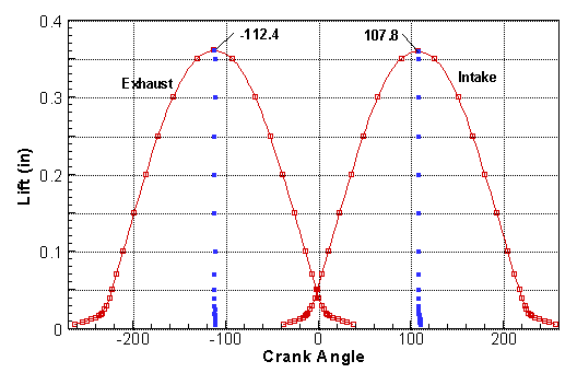
So the process is to turn the crank and cam until you see the desired lift on the dial indicator (eg 0.100", 0.150", 0.200") on the opening side, then again on the closing side (0.200", 0.150", 0.100"). Armed with all those measurements, you can plot out your results, somewhat similar to this (but with fewer points):
DegreeCam.gif


Then the average of the angle at each opening lift vs the angle at each closing lift (the blue dots in the plot) gives you a more accurate measurement of the exact centerline of each lobe. Then you can choose your sprocket position to get the centerlines as close as possible to the same distance from TDC, but a little bit advanced. The plot shows 2.3 degrees of advance, which is just about perfect (since the chain will stretch a tiny bit in operation, retarding the cam just a little).

But again, unless you're going to modify components (eg offset buttons or a sprocket with a vernier timing adjustment), you only get to make an adjustment in 4 degree steps. Measuring something you can't change (valve timing to better than 1 degree) doesn't make a lot of sense to me; except as a double-check that your cam is ground correctly.

Plot is from https://www.tildentechnologies.com/Cams/Tip_DegreeCam.html which also has a downloadable Excel spreadsheet to help you create your own plot.
 

Attachments

  • DegreeCam.gif
    DegreeCam.gif
    6.5 KB · Views: 77
Great, thanks Randall. I'll go back and re-read those materials again with that understanding in mind.
 
If you follow randals original post for setting TDC and then setting #4 cylinder in overlap (both valves open equally),you should just be able to put th etiming geat inthe right place. Remember #4 overlap is #1 firing.
 
Back
Top