• Hey Guest!
    British Car Forum has been supporting enthusiasts for over 25 years by providing a great place to share our love for British cars. You can support our efforts by upgrading your membership for less than the dues of most car clubs. There are some perks with a member upgrade!

    **Upgrade Now**
    (PS: Upgraded members don't see this banner, nor will you see the Google ads that appear on the site.)
  • When posting a classified ad, you MUST select a prefix from the drop-down next to the subject line. If you don't you will get an error and your ad will not be posted!
Tips
Tips

TR2/3/3A New TR3 alternator

TFB

Jedi Knight
Country flag
Offline
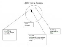
I just recieved my new alternator.Its a new OEM kubota ,Nippondenso clone replacement,40A internal reg.
I ordered the correct plug,which fits.Its 2 wires,green and yellow,marked 14 awg.I thought it would be 8 or 10 gauge ,not 14gauge.
Did I get the right plug or am I missing something?
Thanks
Tom
 
If it is like mine, the high current output does not go through the plug. There is a separate post & nut for the high current connection.
 
Randall,Thanks for reply.I have been surfing for a diagram ,as one did not come with alter.I will contact vendor for diagram tomorrow ,but now I realize it is most likely like yours.Stud for output, plug with green for ground and I guess yellow is 12v to the alternator?
Thanks
Tom
 
Sorry, can't help there. Mine has 3 wires in the socket, but I don't have the plug yet, so no idea which color is which.

However, it's rare to find the ground going through the plug (it has to handle just as much current as the output, so usually it goes through the case & mount). On mine, I'm pretty sure the three wires are
1) Sense (goes to battery)
2) Indicator (goes to lamp on dash)
3) Ignition (gets power when key is on)

Most common, I believe, is for 2-wire plugs to only have functions 1) and 2); but there are many other variations.

Maybe Art (martx-5) will be along, he might know.
 
Randall,I assumed green was ground.
Just checked with fluke.Green wire spade has 6k ohms to frame ,yellow has 16m ohms to frame.
not sure what that meand.
Thanks
Tom
 
Not much unfortunately, as your meter doesn't use enough voltage to forward-bias any of the transistors.

This might help:
 

Attachments

  • 22870.gif
    22870.gif
    21 KB · Views: 732
ok,its type 1 for the plug.The green wire is on terminal IG , ignition switched 12v supply.
Does this mean that power from the load side of ignition switch goes to coil,and this termial?
Is this exciter voltage.
Thanks again Randall,
Tom
 
The place that sold me my Nippondenso alternator gave me this diagram. It doesn't agree with Randall's. However, since I installed the alternator, I discovered that I have a 2-3 amp drain when the ignition is off, so I could have mine wired correctly (though it seems to work just fine when the car is running).
 

Attachments

  • 22871.jpg
    22871.jpg
    23.8 KB · Views: 672
Darrell,Thanks for diagram.
That looks like what I have but the alt. is lsited as replacement for nipp. 100211-4520.
Yes,doesnt match Randalls Brise diagram.
I guess you meant " I could have mine wired incorrectly"
Does your dash light work?
Thanks
Tom
 
Tom,

How much did you pay? My Kubota has a 40A alternator but my brother needs to upgrade the dynamo on his tractor to an alternator.
 
Using the OE number 100211-4520 (Lester #12190), I come up with this regulator, which is an IG, L as type #1 shown in Randall's attachment.

Also, the other unit linked to, 100211-1670 (Lester #12179) also uses the same regulator with the IG, L pins.

IG = Switched 12V to this terminal
L = Dash Lamp to this terminal
 
Darrell_Walker said:
The place that sold me my Nippondenso alternator gave me this diagram. It doesn't agree with Randall's. However, since I installed the alternator, I discovered that I have a 2-3 amp drain when the ignition is off, so I could have mine wired correctly (though it seems to work just fine when the car is running).

That diagram does not look right to me, especially if the unit really is a Lester 12180. The 12180 uses essentially the same regulator as the other units mentioned, with the IG, L terminals. The only difference is that the Lamp terminal is capable of supplying several amps of current for accessory use.
 
Art,Thats good news.
I guess the only disadvantage of the 3wire vs. 4 wire is that the sensing is internal,sensing battery voltage at the alternator,rather than actualy at the battery?
If that is true,would it be getting battery voltage indication from + or IG?
If its IG I may want to use relay to minimize any voltage drop through the switch,or if + go to 8 gauge and keep length as short as possible?
Thanks again
Tom
 
Actually there just isn't a sensing function in the regulator. For whatever reasons, the engineers decided it wasn't necessary for the application. I wouldn't worry about small voltage drops at the IG terminal. Keep the voltage drops as little as possible from the main battery stud back to the battery, and you'll be OK...good connections and heavy (preferably 8 gauge) wire.

I have a Delco 10SI on my TR3, and it has a sense wire, but since I'm using 8 gauge wire back to the battery, I just ran the sense terminal to the alternator battery stud.

Just as a point of interest, when we test for the sense terminals at work, we put two diodes in series with the sense terminal. The two diodes cause about a one volt drop. We check to see that the regulator responds with a like increase in charging voltage.
 
TFB said:
Darrell,Thanks for diagram.
That looks like what I have but the alt. is lsited as replacement for nipp. 100211-4520.
Yes,doesnt match Randalls Brise diagram.
I guess you meant " I could have mine wired incorrectly"
Does your dash light work?
Thanks
Tom

Hi Tom,

Yes, I meant incorrectly. From later posts, it certainly looks like the Nippondeno alternator doesn't have a "sense" wire, though I wired mine as if it did. My dash light does work.

-Darrell
 
Back
Top