
-
 Hey Guest!
British Car Forum has been supporting enthusiasts for over 25 years by providing a great place to share our love for British cars. You can support our efforts by upgrading your membership for less than the dues of most car clubs. There are some perks with a member upgrade!**Upgrade Now**
(PS: Upgraded members don't see this banner, nor will you see the Google ads that appear on the site.)

Tips
- We have a special forum called "Member Articles" where you can submit actual articles for consideration for publication. Learn More
- Don't have an Avatar? If not, your avatar will default to the 1st character in your username. Go into "Account Details" to change your Avatar.
- Some basic forum navigation info: click
 Hey - did you know if you click on the title of a thread it will take you to the first unread post since you last visited that thread?
- Hey Guest - Is your British Car Club in our Clubs database? If not, send me a PM - Basil

- Looking for a local club? Click the "Clubs" tab above and browse hundreds of clubs world-wide.
- Add Android or iPhone APP: click
- Did you know - any picture or video you add in your posts in any marque-specific forum will also get added to the Media Gallery automatically.
- A few more tips about posting and replying: click
- Hey there Guest - be sure to keep your profile page up to date with interesting info about yourself: learn more
- More tips and tricks on Posting and Replying: click
 but were afraid to ask:
  STOP!! Never post your email address in open forums. Bots can "harvest" your email! If you must share your email use a Private Message or use the
  smilie in place of the real @
- Want to mention another member in a post & get their attention? WATCH THIS

- So, you created a "Group" here at BCF and would like to invite other members to join? Watch this!
- Hey Guest - A post a day keeps Basil from visiting you in the small hours and putting a bat up your nightdress!
- Hey Guest - do you know of an upcoming British car event?
 Pretty Please - add it to our Events forum(s) and add to the calendar! >> Here's How <<
- Hey Guest - you be stylin' Change the look and feel of the forum to fit your taste. Check it out
- If you run across an inappropriate post, for example a post that breaks our rules or looks like it might be spam, you can report the post to the moderators: Learn More
- If you would like to try some different "looks" or styles for the site, scroll to the very bottom, on the left and click the Style Selector.
You are using an out of date browser. It may not display this or other websites correctly.
You should upgrade or use an alternative browser.
You should upgrade or use an alternative browser.
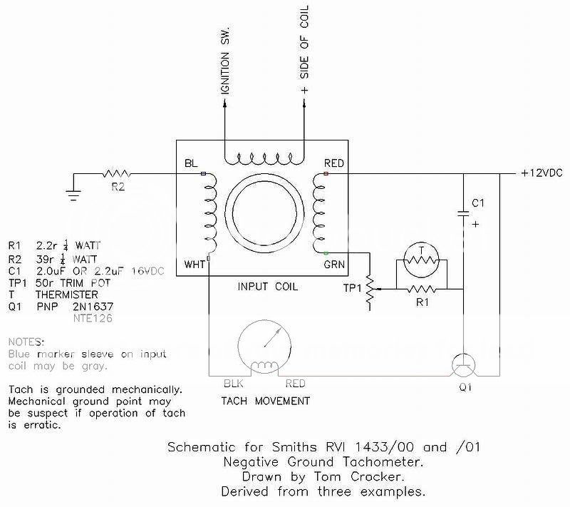
New! Schematic for Smiths RVI tachometer
- Thread starter 58Custom
- Start date
OP
58Custom
Jedi Warrior
Offline
jlaird said:Needs to go in the wiwi.
Good idea. I have some DC resistance measurements of the coils and the meter coil to add as well. Unfortunately, I am unable to regester as the random code generaqtor is not working with either IE7 or Firefox.


regularman
Yoda
Offline
Ah, yes the single transistor one. I have one of those. I was going to fix it but it had a broken spring and at that point it becomes like a watch.
OP
58Custom
Jedi Warrior
Offline
DrEntropy said:In th' ~wiwi~ ?!?! ....eeeewwww.
Tom, R1 & R2 and pot in ohms, yes?
I had a schematic to "convert" the Lotus one from pos-to-neg long ago but can't find it now. And want to do it with the B tach... any "hints"? An RVI 2401 /008.
Yes. 2.2r is 2.2 ohms. I will change that to ohms to make it simple. While I am updating that, I will add the DC resistance measurements I got for the input coul and the meter coil.
I don't have any prior knowledge about these or knowledge of the other types and I can't help with polarity conversions. I got into these because of necessity. Mine is still acting up. I plan to replace the cap and see what that will do. After I located and fixed the intermittant ground, it worked OK once. Now it reads high at idle. Grr.

Offline
According to my copy of Astley's book (<span style="font-style: italic">MGB Electrical Systems</span>), the potentiometer should be 150 ohms and the resistor 22 ohms. The color codes can get dark on old resistors, then a brown band looks black and so on. Then they can be quite hard to read. Especially in car electronics, which get hot and are not in a clean environment.
The coil resistance measurements should also be useful to have--that's the kind of thing that you usually can't find unless you have a known working unit to measure. But, when you want to know it, it's usually to check a meter you aren't sure is working.
The coil resistance measurements should also be useful to have--that's the kind of thing that you usually can't find unless you have a known working unit to measure. But, when you want to know it, it's usually to check a meter you aren't sure is working.
Offline
Of course, there is no guarantee that Astley is correct, either--I've found a couple errors in his book. However, it seems clear to me that the 22 ohm resistor is right, and the 150-ohm pot could be OK. If you have 50, and it hits the stops before you can get the tach to read the right value, just add another resistor of 50-100 ohms or so in series with it.