• Hi Guest!
    If you appreciate British Car Forum and our 25 years of supporting British car enthusiasts with technical and anicdotal information, collected from our thousands of great members, please support us with a low-cost subscription. You can become a supporting member for less than the dues of most car clubs.

    There are some perks with a member upgrade!
    **Upgrade Now**
    (PS: Subscribers don't see this gawd-aweful banner
Tips
Tips

Need some help, electrical issue

The more advice the better, we want this to be safe and right!...

Thats a great way to explain it, the switch did act like a fuse. Just ordered the replacement and will go back and order the relay too, great advice.

Anyone have a cheat sheet on installation of the relay handy? Wel start to look now, might be on the Moss site....

As always, well post the pics:>)

Kurt
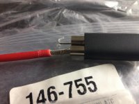
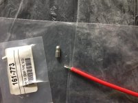
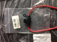
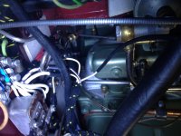
Now, were adding in all the inline fuses and will post a couple pics....

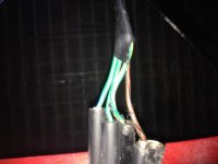
Since you now know the switch acts as a good fuse you should install a relay to activate the head lights.
Then all the load the switch sees is the relay coil.
 
Personally, I wouldn't use in-line fuses if I could avoid it. I replaced the fuse block with one that had more circuits on it.
 
Your right. I should use the fuse block, much more simple but want to try to hide all the added fuses. I cant think of a good place in the engine bay to put it, so was just doing in-lines under the dash and boot.

I have seen blocks in a few pics, and when in the open, to me take away from the beauty of simplicity, right or wrong.... I will do the relays for the lights also, again, trying to find the right hiding space.....I suppose it doesnt matter at the end of the day how something looks, its more about the safety and piece of mind, so this was my compromise....

Personally, I wouldn't use in-line fuses if I could avoid it. I replaced the fuse block with one that had more circuits on it.
 
Well if you do not use those clumsy glass inline fuse holders.
Installing inline fuses can be considerably cleaned up.
Use those small APM, ATM square blade type plug in fuses that hide inside a rubber hat.
Cut the leads as short as practical and solder on bullet connectors then slip it in your selected circuit.
 
Last edited:
Although I can appreciate the centralizing use of a larger fuse block, it will require that any additional fused circuits be wired to a central point…the block. With a limited number of available fuses, you may be restricted on the number of circuits/sub-circuits/components you can protect. However, if a complementing approach is taken, fuse blocks can be added as required and installed incognito (i.e. under the dash or other hidden convenient location). Still, a block requires routing covered circuits to its specific location and this may eliminate the addition of some protection (i.e. license plate light). So, for those wanting the flexibility to selectively limit risk by adding protection, a fuse block may not represent a total solution.

An in-line fuse setup has 4 basic benefits:

  1. Easily placed on a specific circuit or component of a circuit you want to protect without a having to consider a limit of available fuse.
  2. Easily sized to the amperage requirement or type of response desired to protect a specific protection requirement (i.e. a 20amp circuit breaker for the headlights or a 5amp sub-circuit fuse for on the light-installed reflectors).
  3. Easily hidden to maintain an original appearance.
  4. Easily added or eliminated without affecting other circuits or components.

Mixing complimenting fuse blocks with in-line fuses that have been installed to address discrete concerns (i.e. OD Solenoid, fuel pump, etc.) may be a more ubiquitous approach and provide most of what the centralization and discrete distributed approaches have to offer. Since you are integrating extended protection into an present and functioning electrical system, designing a solution outside of the context and restrictions of what exists is neither practical or efficient and choosing one approach (i.e. centralized fuse block or distributed in-line fuse) will only restrict. IMO, there is no one way to address the extension of electrical protection in your Healey, so enjoy yourself and create your own multi-faceted approach.

Good luck,
Ray (64BJ8P1)
 
Last edited:
Guys, the inline-fuses are in and have a question. The wire for the in-line fuse is 12 awg and the largest bullet connector Moss has is 14. Is it ok if we make the connection by placing the wire in the connector here and crush? That lets me use the proper bullet connector on the other end to tie in.

For placement:

OD wire, closest to top?
Fuel next to pump?
Horn, behind grill?
Rear Tail, under boot lip?

I also have the have the relay kit recommended on the way for headlights and Rays instructions to follow, hopefully this weekend!.
 

Attachments

  • photo 3 (2).jpg
    photo 3 (2).jpg
    196.1 KB · Views: 75
  • photo 2 (1).jpg
    photo 2 (1).jpg
    193.8 KB · Views: 77
  • photo 1 (2).jpg
    photo 1 (2).jpg
    192.6 KB · Views: 76
  • photo 2 (2).jpg
    photo 2 (2).jpg
    173.2 KB · Views: 72
  • photo 1 (4).jpg
    photo 1 (4).jpg
    186.5 KB · Views: 81
Is it ok if we make the connection by placing the wire in the connector here and crush?

I did not say anything about CRUSH !!----Keoke---:angel2:--------:lol:
 
hahahah, what a word, CRUSH. That was the best description we had :>). Heres a pic of what were thinking of crimping.

Is it ok if we make the connection by placing the wire in the connector here and crush?

I did not say anything about CRUSH !!----Keoke---:angel2:--------:lol:
 

Attachments

  • photo (1).jpg
    photo (1).jpg
    202.8 KB · Views: 72
Is it ok if we make the connection by placing the wire in the connector here and crush?

i think a better solution would be to remove the metal barrell from the insulating shell and solder the wire to one side of the double connector barrell, then slide the insulating sleeve back on.

Those female bullet connectors are not made to be crimped and that would make a very unreliable connection.

Also I would use a single connector rather than a dual if that would work for you
 
Geeze, thats so smart and simple. :encouragement: 
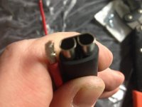
Thats experience for ya! Thank you and will do. Well post the pics....

Is it ok if we make the connection by placing the wire in the connector here and crush?

i think a better solution would be to remove the metal barrell from the insulating shell and solder the wire to one side of the double connector barrell, then slide the insulating sleeve back on.

Those female bullet connectors are not made to be crimped. . Also I would use a single connector rather than a dual if that would work for you
 
Hi KKaa
Sorry I find late this tread.
I have a PDF article for easy installation
on 100/4 relay on Head Light-
It appeared on September 2010 at page 16 of the
AUSTIN HEALEY OWNERS CLUB magazine
author Don Hardie- on TIPS for the Weekend Mechanics

It can be used also on 100/6 models

I have one copy PDF of it that I can transmit to you but I need you email address.

NOTE My copy haven't satisfying good quality
especially on the wire diagram zone-- so the ORIGINAL article must be FIND if you want follow this way

This article can help you for the ORIGINAL Head Lamp switch repair
https://www.lotus-europa.com/manuals/misc/electrical/head_sw.html
Cheers
 
Good answer Kioke.

Kurt, when making these connections, I would suggest filling the connectors with dielectric grease to virtually eliminate the penetration of moisture and the formation of corrosion.

Most Lucas issues are the result of bad connections and the formation of insulating corrosion. This formation, due to temperature change and moisture penetration (from humidity), results in uncertain connections. I have done this when first restoring my Healey in 1980 I soldered all bullet connectors to the connected wire and, after cleaning the receivers, filled them before inserting the bullets. Today, I have good clean contacts that are easily withdrawn (with a proper level of resistance) and no electrical failures due to this issue. I also suggest you do this on all ground bolts and connections related to the installation of your upgraded headlights.

Keep in mind that dielectric grease is a nonconductive that moves aside with the application of pressure (i.e. connectors or screw/bolt thread pressure) leaving a air/moisture insulating film adjacent to the points of contact.

Enjoy,
Ray (64BJ8P1)
 
Ok, perfect and great advice. We were able to do the OD, and rear tail tonight. Used the crimping kit from Moss with the bullet connectors for all the ends, so came out clean...On to the fuel, horn, and wipers tomorrow, then headlamp relay. Will post the pics tomorrow....

Good answer Kioke.

Kurt, when making these connections, I would suggest filling the connectors with dielectric grease to virtually eliminate the penetration of moisture and the formation of corrosion.

Most Lucas issues are the result of bad connections and the formation of insulating corrosion. This formation, due to temperature change and moisture penetration (from humidity), results in uncertain connections. I have done this when first restoring my Healey in 1980 I soldered all bullet connectors to the connected wire and, after cleaning the receivers, filled them before inserting the bullets. Today, I have good clean contacts that are easily withdrawn (with a proper level of resistance) and no electrical failures due to this issue. I also suggest you do this on all ground bolts and connections related to the installation of your upgraded headlights.

Keep in mind that dielectric grease is a nonconductive that moves aside with the application of pressure (i.e. connectors or screw/bolt thread pressure) leaving a air/moisture insulating film adjacent to the points of contact.

Enjoy,
Ray (64BJ8P1)
 
Kurt,

The horn is fused with the 35 amp fuse (50 amp Lucas) in theoriginal block. This is because itrequires a substantial amount of power to vibrate the diaphragm. Realize that, although it is not soundedoften, when it is, it really draws (especially when corrosion forming in thehorn over years). Some have gotten away using lower amperage fuses, however, this is not part of its standard and, when needed, may not have sufficient power to be driven.

When considering a lower amp fuse, also consider reducingthe amperage required to flow through the steering wheel and horn button. These are vulnerable areas and the gauge of themultiple (horn/directional) wires passing through the steering column is quitethin and in tight proximity.

One alternative is to install a relay (hidden) behind thesupport on which the horns are mounted. Power for the relay can be split from the fused-supply feeding the headlights. This would require only a small fraction ofthe original power, needed to switch the relay, to pass through the column to,and across, the horn button.

Because the horn is usually the least used electricalcomponent in the car, it is usually ignored or even forgotten. However, remember the horn button actuallygrounds the circuit and a broken or bare horn column wire would be open to a significantburn, even without pressing the button, before its 35 amp fuse is blown.

Good luck,
Ray (64BJ8P1)

 
However, remember the horn button actuallygrounds the circuit and a broken or bare horn column wire would be open to a significantburn, even without pressing the button, before its 35 amp fuse is blown.

The horn wiring in the column is a ground wire, so if it frays and touches the body, the horn will sound. As far as I can see, power flows from the fuse block directly to the horns without any connectors.
 
If you want to use the dash switch you might want to replace it with a switch like the light switch. That will give you two settings. Dash or dash and under dash.
 
HA! thats right, hahaha. If I did it the way I explained, we'd have foot-well lights when we turn on the dash lights, hahahaha.

Does anyone know of a switch that can replace the panel light switch and do this? So, same size but be on - dash, off, or on all? Like this but the three functions?

https://www.ahspares.co.uk/austin-healey/big-healey/Electrical-Switches/PANEL-LIGHT-SWITCH.aspx

If you want to use the dash switch you might want to replace it with a switch like the light switch. That will give you two settings. Dash or dash and under dash.
 
Back
Top