Hi Guest!

 Hey - did you know if you click on the title of a thread it will take you to the first unread post since you last visited that thread?
 but were afraid to ask:
  STOP!! Never post your email address in open forums. Bots can "harvest" your email! If you must share your email use a Private Message or use the
  smilie in place of the real @
 Pretty Please - add it to our Events forum(s) and add to the calendar! >>
tmc
Senior Member
Offline
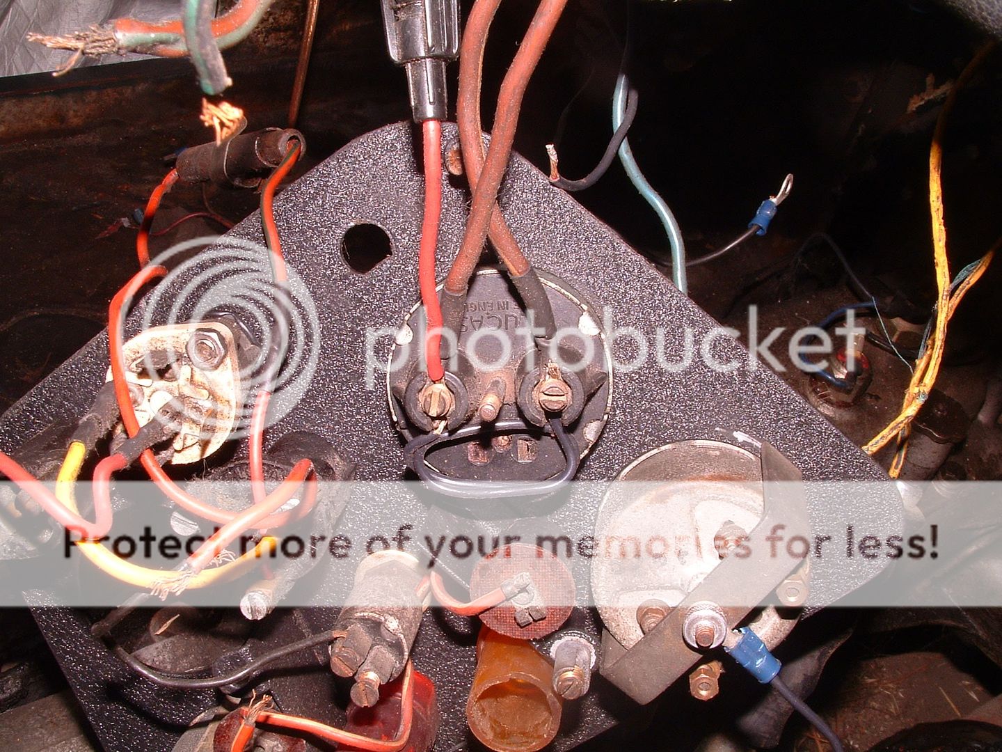
This is follow-up to earlier posts about my wiring project. I've laid the harness out in the car and starting to ID where each wire goes, labeling them, etc. I have several questions at this point, some of them naive, I'm sure!
1. The harness has a number of wires that end at blunt connectors. It appears to me that I have to create the wiring between those connectors and various components.......like the horns, front signal lights, the steering column harness, the brake switch on the right front chassis, etc. To keep to "original", I need to match the wire colors to the harness I have......any suggestions?
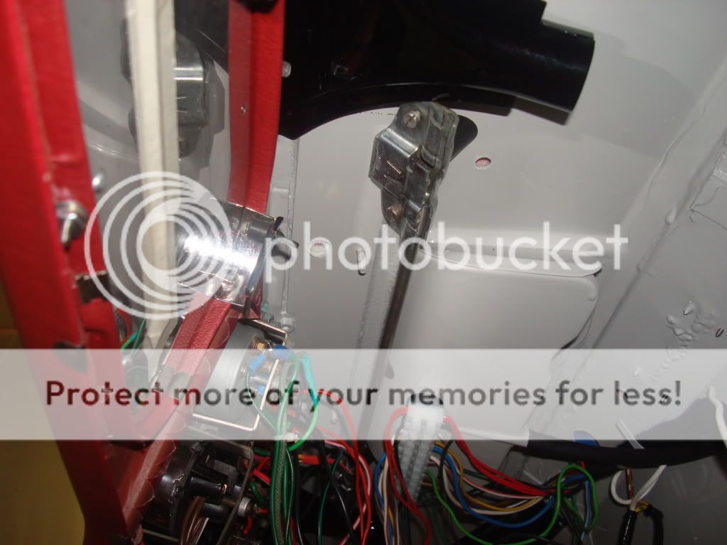
2. There's a grommet that seals the hole where the wiring harness comes through the firewall......how to you fit the grommet over the harness, other than slitting it?
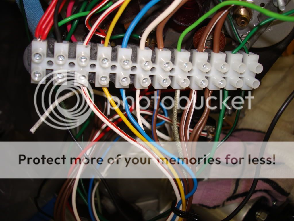
3. I have a heavy brown wire, with a little green slip on "tag" that extends forward and also appears with the cockpit portion of the harness......can't find that wire anywhere on the wiring diagrams. All the purely brown wires seem to be accounted for between the fuse box, ammeter, and starter solenoid.
4. The wires that end "bare" need to be "tinned"......I take that to be solder to hold them together and not fray?
1. The harness has a number of wires that end at blunt connectors. It appears to me that I have to create the wiring between those connectors and various components.......like the horns, front signal lights, the steering column harness, the brake switch on the right front chassis, etc. To keep to "original", I need to match the wire colors to the harness I have......any suggestions?
2. There's a grommet that seals the hole where the wiring harness comes through the firewall......how to you fit the grommet over the harness, other than slitting it?
3. I have a heavy brown wire, with a little green slip on "tag" that extends forward and also appears with the cockpit portion of the harness......can't find that wire anywhere on the wiring diagrams. All the purely brown wires seem to be accounted for between the fuse box, ammeter, and starter solenoid.
4. The wires that end "bare" need to be "tinned"......I take that to be solder to hold them together and not fray?