• Hi Guest!
    If you appreciate British Car Forum and our 25 years of supporting British car enthusiasts with technical and anicdotal information, collected from our thousands of great members, please support us with a low-cost subscription. You can become a supporting member for less than the dues of most car clubs.

    There are some perks with a member upgrade!
    **Upgrade Now**
    (PS: Subscribers don't see this gawd-aweful banner
Tips
Tips

TR2/3/3A More wiring questions?

karls59tr

Obi Wan
Bronze
Country flag
Offline
1.There is green wire that is attached to the back of the Ammeter with a ring terminal.There is another 6" green wire that runs off that ring terminal. What is that wire for....can't see anything on the wiring diagram for it? Also does the green ring terminal wire still go to the "B" side of the Ammeter if I have switched the system to NEG ground?

2.The hollow bullet like "caps" for the ends of the tail light wiring.(do they have a name?). Is the proper way to connect them to push the stranded wire out the small hole on the end of the cap,splay the strands out and push the cap on to the tail light wiring mounting holders or is solder required?

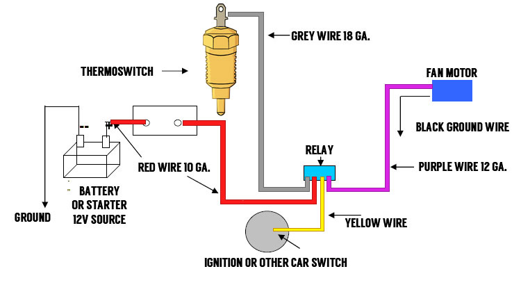
3.I'm adding a 4 fuse Lucas fuse box in addition to the existing 2 fuse box to wire in an electric fan and possibly the headlights. Where can I tie in the power source other than the ignition switch if that is too crowded. Run wires from the solenoid???

Any advice appreciated.:eagerness:
 
Karl,
1. That wire on the ring terminal should be BLACK and is the ground and should run from gauge to gauge to provide the grounds needed for the dash lights. The ammeter wires should be a heavy brown wire.

2.Yes, I believe they put them on that way so the tail light gets can be removed and replaced. Soldering them makes it more difficult to run the wires through the gasket. But soldering them gives you a much better connection. I have never seen any different name then bullet connectors for these.

3. I understand that fusing the headlights is a bad idea.
Some people set up their fan to allow it to run after the engine is shut off via a thermostatic switch. So it depends on what you intend to do.
Charley
 
1. Has to be an add-on, not original. Charley may be right about it being a ground wire, but there is no reason to ground the ammeter. I suggest either chasing down what it is connected to, or leaving it disconnected (insulated so it can't short) and seeing what doesn't work.

2. I believe Lucas called those "fold the wire over" bullets "sleeve, terminal". I refuse to have them on my car; install a proper bullet (either solder or crimp) and have one less thing to worry about.

3. If you power the fuse block from the solenoid, then any current drawn through the fuse block will discharge the battery without showing up as discharge on the ammeter. I linked mine to A1 on the control box.
 
Charley
Not the black ground that you mentioned. The green wire that comes from the fuse block and goes to the "B' side of the Ammeter also has a ring terminal to connect same...there is an additional 6" wire running off it??

Randall
I should have mentioned that I have removed the control box and installed an Alternator. I have a repro Lucas 4 fuse box that I had planned to install beside the original 2 fuse block.
Is the ignition switch the "only" place I can get power to run from there to the new fuse box...then to the switch...then to the fan? Or say I have other items I want to connect to the new fuse block....where could I get power from if the ignition switch is overcrowded? Electrical is not my forte.:fat:
 
Karl,
Like Randall says, that green wire must be an add on. I believe that the wires to the ammeter are live all of the time and unfused. So any wire connected to them would be hot. Green wires in these wiring systems is meant to be a fused wire. I agree with Randall leave it off until you find need for it and make sure it is safe to use.
Charley
 
Running the radiator fan directly from the ignition switch is probably a bad idea. The fan draws a lot of extra current when it is first starting up, and the switch isn't designed to control such a large current. (Mine got quite warm and probably would have failed relatively soon if I hadn't done the relay thing.) Also, if the fan switch happens to be closed when you turn the ignition off, the fan motor will act like a generator for a second or two, and keep the engine running. Not really a problem, but annoying. So I suggest using a relay, which can be wired something like
relay.jpg

https://www.championradiators.com/Thermostat-relay-kit-instruction

The terminal on the original fuse block with the white wires would be another place to tap into the output of the ignition switch. The 'hot' terminal on the starter switch would be another.
 
Back
Top