• Hi Guest!
    You can help ensure that British Car Forum (BCF) continues to provide a great place to engage in the British car hobby! If you find BCF a beneficial community, please consider supporting our efforts with a subscription.

    There are some perks with a member upgrade!
    **Upgrade Now**
    (PS: Subscribers don't see this gawd-aweful banner
Tips
Tips

MegaJolt installation

Westfield_XI

Jedi Warrior
Offline
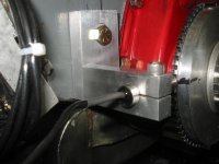
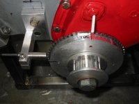
Has anyone here ever installed a MegaJolt electronic ignition here? I am curious as to my options regarding the crank trigger and how it gets attached to the damper. Most info seems to be from the UK and is for turbo'd mini's.
 
No info on a megaJolt, but I've installed a few Electromotive ignitions in my lifetime. Here's few picture of a Electromotive trigger wheel and a pick up sensor on a dry sump 948 race motor, The installation of one of these on a stock harmonic balancer is something I've done a few times as well, it was mounted the backside of the harmonic balancer, we used a shim to not let it make contact with the outer ring of the stock balancer, the wheel itself was mounted on the inner ring of the balancer.
 

Attachments

  • 8920.jpg
    8920.jpg
    41.3 KB · Views: 201
  • 8921.jpg
    8921.jpg
    45.4 KB · Views: 209
Ha, dry sump. Now that should keep the rear seal from leaking.
 
Are we talking cost here or solutions, LOL.
 
Well, with <u>your</u> money......... /bcforum/images/%%GRAEMLIN_URL%%/grin.gif
But, with a dry sump, you would have to find a place for the reservoir, and that usually goes in the passengers footwell. Kay may find it hard to ride along! /bcforum/images/%%GRAEMLIN_URL%%/grin.gif
Jeff
 
Hap, I was running a similar pickup on the test engine but ran into severe vibration problems with the mounting bracket. Enough to cause the sensor to strike the pulley when the engine was at resonant frequency of the bracket. All I could do was to stiffen the bracket until it's resonant frequency was above the engine's top speed. And that's high. It is exactly horizontal vibrations that are First, lowest frequency, and Second, those that will allow sensor - pulley contact.
 
I had the same problem on a 1500, Donn. I ate two pickups before I figured it out and redesigned the bracket with an added gusset to raise the resonant freq.
Jeff
 
Thanks for the tip, my crank is wedged and all moving parts are balanced, but you can't be too careful. The MJ kit shipped today, we shall see how easily it goes together. I have a friend with a salvage yard who will get the EDIS4 box, VR sensor and crank trigger for me for free. If I can figure out how to attach the crank wheel to my damper w/o damage I am home free. If this works I will have a new dist. with pertronix kit inside for sale.
 
Hap, did you weld/braze the trigger wheel to the damper, or is that too much heat? I was thinking of machining the trigger wheel to be a light press fit assisted by epoxy and screws. Is this possible?

My engine is in LA and I am in AZ, but IIRC I have a gilmer belt drive primary with cogged belt drive to the miniature alternator. I am not sure which damper APT used, will have to call and ask on Monday.

The Ford 36-1 triggers come in many dia.s even a pressed sheetmetal lightweight version. The trigger and sensor are a universial fit: only the EDIS computer comes in 4, 6 & 8 cyl versions, any 4-cyl box will work.
 
My 1500 was balanced to the Nth degree too, but it still would set up a vibration in the pickup bracket. With the clearance between the pickup and the rluctor wheel only at about .012", it doesn't take much movement for the pickup to contact the wheel.
There are other causes of vibration not related to engine balance to consider. One of my failures was due to a brief off track excursion for example.
Jeff
 
Jeff, where did you mount your pickup bracket on your 1500? An EDIS set up is on my short list of future projects.
 
Morris, I put it on the right side of the front plate. One of the mount bolts went into an existing hole into the block, and the other was through the plate with a nut and bolt. I don't think I've got any pictures, but I'll check.
I put the trigger wheel on the aluminum crank pulley I made.
Jeff
 
It is an oil system where the oil reservoir is located remotely outside the engine versus the wet sump system we see on most street cars.

Here is a link to a short informative article explaining what it is and some of the advantages over a wet sump:

https://auto.howstuffworks.com/question331.htm

I've got a race engine set up for a dry sump system and all the stuff to install on the car -- only need the time and initiative to get 'er done. /bcforum/images/%%GRAEMLIN_URL%%/driving.gif

Tim
 
We attached the trigger wheel to the harmonic balncers with countersunk allen bolts, like 4 #10s.

On the trigger mount, it worked fine, this was a 9000 rpm race motor, and it never gave us any problems. I've also made the trigger from pieces of 1/4" thick aluminum angle as well, so one peice design. For a long time we used set screws to hold the trigger in, but sometime the owners would way over tighten and damage the trigger, so we started making squeeze clamps so that couldn't dent the trigger anymore.
 
Something else to keep in mind is how you have adjust the the timing, on the Electromotive the bracket can be fixed, as you do all your timing adjustment at the box with dials, guys who crank trigger fired thier MSD boxes had to have a more elaborate adjustable bracket because they had to phyiscally move the trigger to change timing.
 
The timing, advance, advance curves are all altered on a laptop and then written to the flash memory on the chip. In case of failure of the computer the system reverts to Ford's "limp-home-mode" of fixed 10 degree advance IIRC. The car will start and drive with the MegaJolt completely removed from the car! The base Ford electronic ignition uses a 36 tooth trigger with 1 missing tooth 90 drgrees BTDC to time the system, the sensor can be mounted anywhere in the 360 degrees of the trigger to simplify the installation. The crank trigger has to be installed to a tolerance of +/- 5 degrees.

There seem to be a lot of people in the UK using this system on all sorts of 4, 6 & 8 cylinder engines with great success. The forced induction Mini community seem to have wholeheartedly embraced this system, thus there is a lot of knowledge of the A-series.

Google MegaJolt for more info, Autosportlabs.com is the developer, but Minfinity is a good place with a good installation manual.
 
Do you have a picture of the area around the dampener with the engine in the car? In a Spidget the dampener is so close to the front cross member that it is difficult to add a 36-1 trigger to the face of the dampener like they do with the Minis. If you have ample room in front of the dampener then go that route. If it is restricted like in a Spridget then my opinion is that the stock dampener needs to be machined. The two ways to do this are to machine a lip in the dampener OD to accept a ring gear style trigger. Set it up for an interference fit and or us a few countersunk machine screws. The other way is to machine notches out of the stock dampener in 10' increments plus the "minus one" tooth for TDC. This requires a lot more setup on the machine but looks slick when installed. I've been trying to find a link to a guy who had the CNC program file to do this but I can't locate it.

One thing:
Westfield_XI said:
The base Ford electronic ignition uses a 36 tooth trigger with 1 missing tooth 90 drgrees BTDC to time the system, the sensor can be mounted anywhere in the 360 degrees of the trigger to simplify the installation. The crank trigger has to be installed to a tolerance of +/- 5 degrees.
I may just not be interpreting correctly what you wrote but the sensor must be located 90' BTDC from the missing tooth. You can located the missing tooth anywhere in the 360' rotation but once it is located then the trigger location is fixed. If yoo have the ability to move the trigger wheel around the you are ok, but if you machine the dampener then the missing tooth needs to be located in relation to the key way such that the sensor can be mounted in a convenient spot.

Don't forget that unlike the Electromotive trigger wheel, the EDIS trigger wheel has to be ferrous.
 
Back
Top