• Hey Guest!
    British Car Forum has been supporting enthusiasts for over 25 years by providing a great place to share our love for British cars. You can support our efforts by upgrading your membership for less than the dues of most car clubs. There are some perks with a member upgrade!

    **Upgrade Now**
    (PS: Upgraded members don't see this banner, nor will you see the Google ads that appear on the site.)
Tips
Tips

TR2/3/3A Lockheed Axle

A slip fit means there is several thousandths clearance on the sides of the splines. Since there is a lot of torque applied in both directions under varying conditions (acceleration one way, hard braking the other), I'm guessing that even with the nut and wedge clamping it, the hub can move slightly on the splines. The motion (the 'fretting' mentioned in Sports/1/F) will eventually wear and damage the splines, allowing them to first leak, and ultimately fail..

I agree completely with the engineering. I'm just looking at the history. It appears even the tight splines did not fix the leaks and breaks problem. Anyway, at this point I would bet any axle left is of the later tight spline design, since they switched to that in the first year of production.

The grease cup is indeed, just a steel insert that was added during manufacture in 1954 to help prevent the grease from washing out of the outer bearings. The service bulletin is meant to retrofit cars that were already on the road.

Looking inside the flange, it looks like a cup going all the way around the inside of the axle tube. It has a steel lip that almost reaches the axle shaft...and that is what confused me looking at it. It looks like a seal made of steel, rather than one with a rubber lip. I assume without this cup, the axle tube would be the same diameter all the way through to the differential.

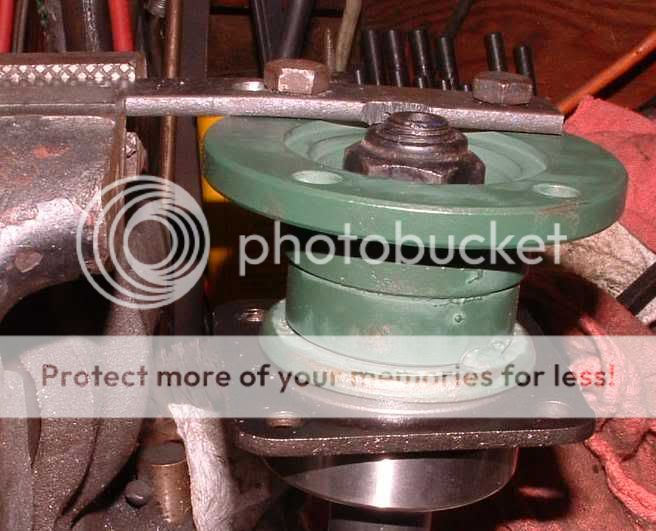
This is a photo of the axle flange as it looks when the axle is just removed. The insert is seen full of grease.

 
Just a few more pics showing the removal of the axles.

Here is how the pumpkin looks after removing the differential back cover...


The next step is to remove the 4 bolts that sandwich the brake backplate and bearing holder. The axle may just pull out at that point. If it is stuck, you can take a small prybar and shove between the spider gear shaft and the inside end of the axle shaft. The shaft is slip fit here, so it doesn't take much to get it moving...


Finally, here is how the axle looks after removal. The hub, brake backplate, bearing holder, and bearing come out with it...


To continue the disassembly, Once the axles are out, it's time to work on the differential unit itself. If you have an axle that you know ran quietly before you pulled it, just unbolt the caps and pull it out. In my case, this is an unknown diff from Marv, so I wanted to check the gear contact pattern first. Do this by spraying the ring gear teeth with anything that has color. In this case I am using white lithium grease.


Once sprayed, work the dif in both directions while putting as much load on the teeth as you can. I have known racers to use the brakes to load the gears and a 3 foot pipe to turn the pinion, so as to simulate the racing load the teeth will see. Now look at the pattern of grease that was removed. The service manual shows good patterns. This is normal for a well used set of gears...


Now, remove the caps holding the pumpkin. The caps are marked from the factory, but I remarked them so I know where they went and which side is up.


Now, the pumpkin is a press fit in the housing. The correct tool is a case spreader, shown in the manual. I can't afford one, and have never needed it. I simply support the axle tubes at the ends, so the center is suspended off the table. I place a towel under the diff and rotate the axle so the diff opening is straight down. Now, lift one axle tube and lit it drop a couple inches back on the support. This spreads the case and allows the pumpkin to drop right out. When it comes out, bag and tag each bearing and shim pack.

 
Now, the only thing left is the pinion.

Important Tip!! This warrants a bit of discussion about both the pinion flange bolt and the wheel hub bolts. If you have an impact wrench, you do not have to loosen these 3 nuts until you are removing the flange/hubs. The impact wrench will use the mass of the assembly and take the nuts right off. But, if you do not have an impact wrench, you need to loosen these 3 nuts before you even remove the axle from the car. If you have reached this point and have not loosened the nuts...you will have to borrow an impact wrench.

Now you need a press (or the Churchill tool). With the pinion flange removed, press the pinion right out of the case. Do Not Hammer the pinion out!! You will be hammering the bearings into their races, which will destroy the bearings. There are 2 shim packs...one between the gear and the large bearing, and the small diameter pack between the small bearing and spacer sleeve.


If you are just replacing specific parts, you can leave the outer pinion races in the case. I removed them, as I planned to sand blast the entire case, and do not want any trapped sand ruining the rebuild.
 
The last thing is the pumpkin. There is a pin that holds the spider gear axle in place. Tap out the pin, tap out the axle shaft, and then the gears can all be spun out of the pumpkin.


Now, you can remove the ring gear if you are replacing it. I am not, so I am not removing it. The ring and pinion are both matched, set up and lapped at the factory as a pair. Removal has the potential to disturb the "set" of the ring that I know from checking is perfect. But, at this point you can bend the lock tabs and remove the bolts. There were early 5/16" ring bolts that are too weak. They were changed during the first production year to 3/8" bolts using lock tabs AND washers. The washers prevent galling of the lock tabs, which would loosen the ring gear over time.

There are thrust washers for the differential and spider gears. Be sure to look them over. If they have excessive slop, there are different sized thrust washers to take up the slop.


And, that is the disassembly. I am busy cleaning parts, but will get back with pictures again when doing the set-up, which is frequently a PITA. So, more to come...
 
Important Tip!! This warrants a bit of discussion about both the pinion flange bolt and the wheel hub bolts. If you have an impact wrench, you do not have to loosen these 3 nuts until you are removing the flange/hubs. The impact wrench will use the mass of the assembly and take the nuts right off. But, if you do not have an impact wrench, you need to loosen these 3 nuts before you even remove the axle from the car. If you have reached this point and have not loosened the nuts...you will have to borrow an impact wrench.
Personally, I dislike using an impact wrench this close to bearings. Probably no real reason, just a phobia of mine after I had several wheel bearing failures from using an impact wrench on a hub nut where the manufacturer specifically said not to (on a different car). Fortunately, there is a fairly easy alternative, shown here removing a side flange for the Stag. The photo shows the bar held in the bench vise, but the approach also works freehand. I used the same bar to change the TR3 pinion seal with the axle still in the car. The bar is just flat bar stock (hot rolled steel) from the local "big box" store (Home Depot). The grind marks are because I didn't get the holes located quite right, and needed some extra space for the socket.

DSCF0002_crop.jpg~original


PS, Thanks for all the photos, John.
 
The axle is back together...but I am down to one question and issue.

The hub presses onto the axle splines, followed by what is called the splined washer. I've got one bad splined washer. To be honest, I am not really sure what this part contributes to the assembly. I would describe it more as a collet. It slides over the axle, and it gets squeezed by the cone shape inside the hub so as to pinch the axle shaft as the nut it tightened. This just seems redundant to me. The axle is pressed into the hub, so what can a tightening collet contribute??

Anyway, if anyone has a line on a splined washer...new or used...I could really use one.

And...along those lines, i still have not found the collars for my wire wheel hubs...just in case anyone runs across those too!
 
John,
thought a had you a line on collars, guy came by and got parts. He said he thought he had some but have never heard back from him.

Marv
 
John,
thought a had you a line on collars, guy came by and got parts. He said he thought he had some but have never heard back from him.

Marv

Thanks for trying...sooner or later I'll find them!

And, Marv, the inside of your axle was in very good shape. All the internals and tooth patterns were great. The only parts I changed were the outer axle bearings and one tapered axle collar. Thanks again...
 
Great Pictures John, I wish I had saved an old differential I had many years ago that had a chipped ring gear to practice on. I was moving and had to get rid of some stuff, so the story goes.
 
The axle is back together...but I am down to one question and issue.

The hub presses onto the axle splines, followed by what is called the splined washer. I've got one bad splined washer. To be honest, I am not really sure what this part contributes to the assembly. I would describe it more as a collet. It slides over the axle, and it gets squeezed by the cone shape inside the hub so as to pinch the axle shaft as the nut it tightened. This just seems redundant to me. The axle is pressed into the hub, so what can a tightening collet contribute??
From reading Sports/1/F, I'd say the engineers felt that the interference fit by itself was not enough, and wanted to keep the increased locking power of the "splined locking collar". Otherwise, they wouldn't have also hardened the collar. That joint can take a huge amount of force, especially when sliding around on a rutted road (eg rallying in the 1950s) and, as noted in the TSB, any movement whatsoever is going to cause eventual failure.

The collar may have also helped center the hub on the shaft. I believe that was clearly the original intent (much like the tapers on wire wheels), and the collar may have still helped even with the larger splines on the shaft. I'm guessing that the tops and bottoms of the splines were still not always a tight press fit into the hub (due to manufacturing tolerances), and that the interference was between the sides of the splines.

Did you try Albert Roth? I've heard conflicting reports as to whether he's sold it off or not, but he certainly used to have an amazing collection of rare and unusual TR parts for sale. Steve Hedke would be someone else to ask; he just might have an entire early axle laying around (from helping someone convert to the later axle) that he would sell.
 
Struck out with Albert Roth...he says he sold out last year on the collars. I have found them from Revington in England, used. I have them ordered. With shipping the collars will cost half what I paid for the whole axle. At least I've found them after than a year of searching...!
 
Back
Top