• Hi Guest!
    You can help ensure that British Car Forum (BCF) continues to provide a great place to engage in the British car hobby! If you find BCF a beneficial community, please consider supporting our efforts with a subscription.

    There are some perks with a member upgrade!
    **Upgrade Now**
    (PS: Subscribers don't see this gawd-aweful banner
Tips
Tips

Is there a negative wire on the directionals?

AUSMHLY

Yoda
Country flag
Offline
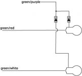
I'm wondering if I can get that last bit of flash bleed-over from my dash directional to cancel out.

I've replaced the two incandescent 2.2 watt bulbs with two led bulbs.
I've replaced the stock flasher unit with an electronic unit. That unit has eliminated almost all of flash bleed-over.

I was reading that installing a load resistor solves this problem.
I've found one that seems like it will work. Directions say, connect one wire to ground and the other wire to the turn/brake wire. I would like to connect it to the directional dash bulb, rather than the actual turn/brake bulb.

I don't see what would be a ground wire.
What two wires would I splice into?
 
What are you calling "flash bleed over"? How does it manifest itself?


A "normal" flasher has a bi-metallic strip that is heated by the bulb current, then bends and opens the load contacts, turning off the bulb.

When you replace incandescent bulbs with LEDs, you must add a resistor from the flasher output to ground to make up for the loss of bulb resistance. LEDs have almost no resistance and the flasher will not operate correctly.

If you have replaced the mechanical flasher with an electronic flasher, you should not need the resistor as the load carrying contacts in the electronic flasher are driven by an electronic clock circuit, not bulb resistance.

If you have a single dash indicator bulb, you can add the resistor between the hot side of the indicator bulb and ground. It won't hurt anything.

Tim
 
Cottontop said:
What are you calling "flash bleed over"? How does it manifest itself?


A "normal" flasher has a bi-metallic strip that is heated by the bulb current, then bends and opens the load contacts, turning off the bulb.

When you replace incandescent bulbs with LEDs, you must add a resistor from the flasher output to ground to make up for the loss of bulb resistance. LEDs have almost no resistance and the flasher will not operate correctly.

If you have replaced the mechanical flasher with an electronic flasher, you should not need the resistor as the load carrying contacts in the electronic flasher are driven by an electronic clock circuit, not bulb resistance.

Tim

Hi Tim,
I replaced the stock Healey flasher with this Napa EL-13 unit.
The front and rear lights flash fine as do the dash indicators. They all flash at the correct speed.

The dash indicators have what I term bleed-over. If I want the left to flash, it flashes bright and constantly like it should. Now the right, it will also flash a little too (bleed-over).

I'm just trying to tweak that last little bit of flash out of the directional, that should not be flashing. Make sense?

Here's a photo of how the load resistor recommends one wire to hot, one to ground.
 
Hi Roger,
The green/purple wires on the dash lights would be the likely culprits in my mind. I wonder if adding diodes on those wires would stop any unwanted voltage. Something like this.
 

Attachments

  • 21547.jpg
    21547.jpg
    10.1 KB · Views: 459
Yes Greg, that should work given that the resitance of the back biased diode is high enough. Course you knew that HUH--Keoke- :laugh:
 
GregW said:
Hi Roger,
The green/purple wires on the dash lights would be the likely culprits in my mind. I wonder if adding diodes on those wires would stop any unwanted voltage. Something like this.

Greg,
What's the difference between a load resistor and a diode.
If a diode will work, what info do I need to get a pair. Something from Radio Shack?

I was originally looking at this product:

25 Watt, 10-12v resistors can be connected across the low element wires to simulate the load of a standard filament bulb. This will solve LED related burnt out bulb warnings. One resistor is required for each bulb. Includes gel filled moisture resistant splice taps. These are not to be used on high element wires or blinker bulbs. Use our 6 or 3 Ohm resistors for those applications.
 
AUSMHLY said:
What's the difference between a load resistor and a diode.
If a diode will work, what info do I need to get a pair. Something from Radio Shack?
Hi Roger,
No expert here, but a resistor reduces the energy coming into it by converting it into heat. So the output will be less than what comes in. Using a resistor as a load for an LED makes the bi-metal contact in the old fashion flasher heat up slower because the flasher sees less voltage (as Tim pointed out). A diode is different in that it blocks voltage completely in one direction but allows almost full voltage in the other direction. A one way valve so to speak. Where a resistor blocks equally in both directions.
Now an LED is a diode, but an LED bulb such as your dash indicator may have more than one diode in the housing. Some bi-color bulbs will have 6 diodes in them. Two for light emission and four for directing the + and - feeds to keep the light emitters from burning out.

I can't remember if your dash bulbs were polarity sensitive or not.

BTW, if you haven't, you should do a wiring diagram of all your custom work. It can get tough troubleshooting your car with all those add-ons and changes. :wink:
 
If a diode will work, what info do I need to get a pair. Something from Radio Shack?

Well let me try and struggle through this.
If a 6 ohm 25 watt resistor will also work with the uprated flasher then:

The Diode should be capable of handling about 5 amps of current with a Peak
inverse voltage of 24 volts or more.This is predicated on the wattage of the resistors shown . Consequently, a higher
current diode might be justified if the wattage of the 6 ohm resistor is higher.However, in either case the parts are small and it will not complicate the installation.

OH!!! by the way them cute little blue things in the picture is the best little electric trouble makers I have ever seen.---Keoke-- :laugh:
 
Roger,

Since your car is negative ground, then Greg's diagram is
exactly backwards how to install the diodes.
....
I would try the diodes, not the load resistors.
Since you are using the electronic flasher, the load resistors
will not do the job. The diodes should do it.
.....
For anyone else reading this, if you are still using the standard flasher instead of the electronic flasher, then the
load resistors would probably help.
....
The voltage rating of the diodes should safely exceed 12 volts. If they are rated any voltage at or above 24 V it would be fine.
The power ( wattage ) rating of the diodes does not have to equal the power rating of the load resistors since you are using the
electronic flasher. The indicator bulb circuit will not draw enough current to worry very much about the power ratings of the diodes.
If you want to know for certain what the power rating of the diodes should be. It needs to exceed the power consumption rating of the LED that we are all using now thanks to you ! If I can find the web page of the place were we ordered them, I would look for power or current rating of the LEDs and then buy diodes that exceed that.
Keoke is right about those little clip shut type of connectors being a bad choice.
I would take a spare LED and attach a diode and then test it with the diode installed in both directions.
In one direction the LED should light up bright , the other way around the LED should be out or at least much dimmer than the correct way. The test shows you two things;
1.. You can verify the correct polarity of the diode in the circut.
2.. When the diode is installed in the wrong, backward, not optimal direction. If the LED lights up at all, it should be dim. That is the most it will ever do when the current tries to bleed through in the reverse direction.

Ed :hammer:
 
Ed_K said:
Since your car is negative ground, then Greg's diagram is exactly backwards how to install the diodes.
Hi Ed,
I'm sure you know more on this than I do. (no sarcasm) But all the schematics I see have the little arrow pointing to negative?
250px-Diode_3D_and_ckt.png
 
Diode representations: PN-junction model, schematic symbol, physical part.

The schematic symbol of a diode is correctly shown above such that the anode (pointing end) corresponds to the P-type semiconductor;--Fwiw--Keoke
 
As I mentioned in the beginning of this post, I'm just trying to tweak out that last bit of bleed over flash from the dash indicator that should not be flashing. I am as most of you guys know, a stickler with the details.

So a shout out to Tim, Greg, Keoke and Ed for taking the time to answer and offer suggestions to this situation. I've been on this forum for a long time now and it's because of the help and advise of the nice regulars like the guys above, that my restoration went as smoothly as it did. And we all know how much we appreciate the help from our Healey brothers. (PS. miss you Dave Russell)

Thanks guys!
Roger
 
Roger,

Sorry I haven't written back for a coupla days. I've been out of pocket.

Is everything OK now ?

Do both indicator lights work as they should ?

What did you end up doing ?

Tim
 
Hi Tim,

I have not moved forward on this, for I do not know what part to get nor where to buy said part. Seems I am not providing enough information on what the specs are for the LED I am running. And I understand that.

If someone else would like to run with this, that would be great. For the present, what I have is acceptable, I'm a perfectionist. Sometimes, not easy being me. :square:

Cheers,
R
 
Yep Greg, Those certainly should work. :hammer:

Diodes contain 200A surge. Peak Inverse Voltage (PIV) is 50. Package of 2

Plenty of margin here.----Keoke :yesnod:
 
Roger,

In re-reading your posts, I read that you only replaced your dash indicator lights with LED bulbs, NOT the 4 corners and you replaced the original flasher with an electronic flasher.
<span style="font-weight: bold">Is that correct ?</span>

With an electronic flasher, you should not have to use any load resistors and if you only replaced the instrument panel indictors, you should not have any problems that require the use of isolating diodes.

I'll bet my allowance that you have a ground lifted someplace. Probably between the two dash indicators.

Please shoot an Email with your phone number to tim(at)ntahc.org I'll call you and see if we can get this straightened out.

Tim
 
OK guys,
Maybe....I have the Tridon EL-13 connected wrong?

What pins on the Tridon go to which wires?
No instructions with the Tridon.

Tridon as photo shows:
X = left
P = top
L = right

Healey flasher unit = diagram:
B = 2green wires (1 wire to fuse box, other to directional indicator switch)
P = light green purple (wire goes to both dash indicator lights)
L = green brown (flasher relay #1)

How I have the Tridon connected:
X 2green wires
P light green purple
L green brown
 
Back
Top