Hey Guest!

 Hey - did you know if you click on the title of a thread it will take you to the first unread post since you last visited that thread?
 but were afraid to ask:
  STOP!! Never post your email address in open forums. Bots can "harvest" your email! If you must share your email use a Private Message or use the
  smilie in place of the real @
 Pretty Please - add it to our Events forum(s) and add to the calendar! >>
GTP1960
Jedi Knight
Offline
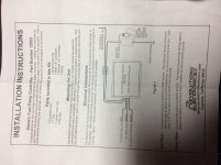
I,m going to install this safety switch tomorrow (I hope).
not sure what the best terminal is for a few of the wires. ( see attached instructions)
i plan to connect the green "tach " wire to my coil, neg. side.: to send an "engine running " signal.
one purple lead goes to the electric fuel pump.
black to ground
the others I am not sure of:
red goes to switched 12v (interpretation?/ suggestions?)
second purple goes to switched 12v or battery (same question?)
is "switched 12v" referring to the starter? Ignition switch? Something else?
any wiring suggestions appreciated, as I am kind of over my head with electrical.
thx & best regards,