Hey Guest!

 Hey - did you know if you click on the title of a thread it will take you to the first unread post since you last visited that thread?
 but were afraid to ask:
  STOP!! Never post your email address in open forums. Bots can "harvest" your email! If you must share your email use a Private Message or use the
  smilie in place of the real @
 Pretty Please - add it to our Events forum(s) and add to the calendar! >>
richie
Senior Member
Offline
Hey all,
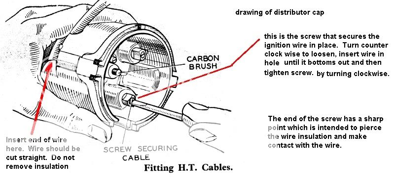
I recently ordered a new rotor and wire set for my TR4A. I am a little unfamiliar with this setup and am curious what the best method is to install these.
It would appear that you just slip the wire end into the cap and screw down the plastic set screw, however it seems that without any thought put into the length of the exposed electrode, I would imagine the current will have no direct path and will therefore be arcing from the actual copper terminal in the rotor to the exposed bit of wire on the leads.
Surely there must be a way to ensure proper contact between the individual terminals in the distributor cap and the wire ends and I was wondering if someone could direct me to a resource explaining this?
Thanks!!