
-
 Hey Guest!
British Car Forum has been supporting enthusiasts for over 25 years by providing a great place to share our love for British cars. You can support our efforts by upgrading your membership for less than the dues of most car clubs. There are some perks with a member upgrade!**Upgrade Now**
(PS: Upgraded members don't see this banner, nor will you see the Google ads that appear on the site.)

Tips
- We have a special forum called "Member Articles" where you can submit actual articles for consideration for publication. Learn More
- Don't have an Avatar? If not, your avatar will default to the 1st character in your username. Go into "Account Details" to change your Avatar.
- Some basic forum navigation info: click
 Hey - did you know if you click on the title of a thread it will take you to the first unread post since you last visited that thread?
- Hey Guest - Is your British Car Club in our Clubs database? If not, send me a PM - Basil

- Looking for a local club? Click the "Clubs" tab above and browse hundreds of clubs world-wide.
- Add Android or iPhone APP: click
- Did you know - any picture or video you add in your posts in any marque-specific forum will also get added to the Media Gallery automatically.
- A few more tips about posting and replying: click
- Hey there Guest - be sure to keep your profile page up to date with interesting info about yourself: learn more
- More tips and tricks on Posting and Replying: click
 but were afraid to ask:
  STOP!! Never post your email address in open forums. Bots can "harvest" your email! If you must share your email use a Private Message or use the
  smilie in place of the real @
- Want to mention another member in a post & get their attention? WATCH THIS

- So, you created a "Group" here at BCF and would like to invite other members to join? Watch this!
- Hey Guest - A post a day keeps Basil from visiting you in the small hours and putting a bat up your nightdress!
- Hey Guest - do you know of an upcoming British car event?
 Pretty Please - add it to our Events forum(s) and add to the calendar! >> Here's How <<
- Hey Guest - you be stylin' Change the look and feel of the forum to fit your taste. Check it out
- If you run across an inappropriate post, for example a post that breaks our rules or looks like it might be spam, you can report the post to the moderators: Learn More
- If you would like to try some different "looks" or styles for the site, scroll to the very bottom, on the left and click the Style Selector.
You are using an out of date browser. It may not display this or other websites correctly.
You should upgrade or use an alternative browser.
You should upgrade or use an alternative browser.
How to Wire an Overdrive?
- Thread starter mgbmedic
- Start date
TR3driver
Great Pumpkin - R.I.P
Offline
I don't have a writeup, but it's easy enough. Here's a diagram from Practical Hints 4th ed, which matched the factory setup on TS39781LO fairly close:
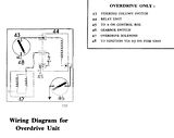
In no particular order:
Mount the relay where you want it (I used the original location on the back of the battery box but almost anywhere will do except on the engine itself.)
Black wire from one side of each isolator switch to ground.
Join other sides together, run a wire to one coil terminal of the relay.
Wire one contact terminal of relay to OD solenoid. TS39781LO originally had some loose PVC sleeving, but I used tight nylon mesh when I replaced the tired old wires.
The other relay contact goes to the battery side of the ammeter. I added an in-line fuse to this line, both to protect the wiring and to perhaps protect the solenoid in case it hung up somehow. The pull-in coil will burn out quickly if something prevents the solenoid from moving all the way, like a piece of gravel. But with a fuse in the line, the fuse will burn out first. I used an MDA-8 "slo blo" since that's what I had on hand, but an ordinary 5 or 10 amp fuse should do fine. The fuse won't heat up enough to blow during the brief instant when the pull-in coil is doing its thing, but will blow if the contacts inside the solenoid don't open PDQ.
The other relay coil terminal goes to one side of the operating switch on the dash.
Although the diagram shows the final wire from the other side of the operating switch going to A3 on the fuse block, the original wire on TS39781LO went to the 'hot' terminal of the starter switch. Since A3 isn't fused anyway, and the short run under the instruments seemed well protected, I kept that arrangement.
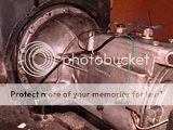
One other thing, I had a lot of trouble with replacement relays not lasting very long, until I added a diode across the solenoid. (Actually the diode is located at the relay, but electrically it is across the solenoid.) The diode is the only polarity-sensitive component; for a negative ground car, the end with the stripe should go to the solenoid wire and the other end to ground.
Here's a shot of the diode, on TS39781LO before I reworked the OD wiring


In no particular order:
Mount the relay where you want it (I used the original location on the back of the battery box but almost anywhere will do except on the engine itself.)
Black wire from one side of each isolator switch to ground.
Join other sides together, run a wire to one coil terminal of the relay.
Wire one contact terminal of relay to OD solenoid. TS39781LO originally had some loose PVC sleeving, but I used tight nylon mesh when I replaced the tired old wires.

The other relay contact goes to the battery side of the ammeter. I added an in-line fuse to this line, both to protect the wiring and to perhaps protect the solenoid in case it hung up somehow. The pull-in coil will burn out quickly if something prevents the solenoid from moving all the way, like a piece of gravel. But with a fuse in the line, the fuse will burn out first. I used an MDA-8 "slo blo" since that's what I had on hand, but an ordinary 5 or 10 amp fuse should do fine. The fuse won't heat up enough to blow during the brief instant when the pull-in coil is doing its thing, but will blow if the contacts inside the solenoid don't open PDQ.
The other relay coil terminal goes to one side of the operating switch on the dash.
Although the diagram shows the final wire from the other side of the operating switch going to A3 on the fuse block, the original wire on TS39781LO went to the 'hot' terminal of the starter switch. Since A3 isn't fused anyway, and the short run under the instruments seemed well protected, I kept that arrangement.
One other thing, I had a lot of trouble with replacement relays not lasting very long, until I added a diode across the solenoid. (Actually the diode is located at the relay, but electrically it is across the solenoid.) The diode is the only polarity-sensitive component; for a negative ground car, the end with the stripe should go to the solenoid wire and the other end to ground.
Here's a shot of the diode, on TS39781LO before I reworked the OD wiring


TR3driver
Great Pumpkin - R.I.P
Offline
Oddly enough, Triumph did the same thing on early Stags. Beats me how that wimpy little switch in the shift knob would stand up to the 20+ amps that the solenoid draws initially, but apparently it at least lasted through the warranty period.Here is something crazy. I have mine wired straight through the switch to the solenoid! I have had it that way for a long, long time. I did it for temporary to start with but have never gotten around to putting a relay in there.
OTOH, Stags are not known for their reliability, so maybe that was just one more feature. I've already had to replace the switch once, even with a J-type OD that only draws a couple of amps. If the new one fails again, I'm going to add a relay.
PS, the diagram that Luke44 gave above is what is in some of the manuals; but not quite the same as what I described (and found on TS39781LO when it came to me). Either one will work fine, I just wanted to point out the difference in case someone is trying to follow both.