• Hi Guest!
    You can help ensure that British Car Forum (BCF) continues to provide a great place to engage in the British car hobby! If you find BCF a beneficial community, please consider supporting our efforts with a subscription.

    There are some perks with a member upgrade!
    **Upgrade Now**
    (PS: Subscribers don't see this gawd-aweful banner
Tips
Tips

Horn Relay

Jim_Gruber

Yoda
Country flag
Offline
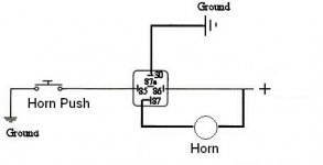
I'm installing a horn relay on Bugsy my '68 Sprite. Since horn receives 12VDC at all times and works by grounding through the contact switch button or on the stalk in this case. How is the relay to be wired. Anyone got a diagram handy. Again all of the diagrams I've seen show 12VDC as switched while our LBC's are simply turning the ground on and off. I can puzzle it out but if someone has something handy I'll save my noggin for our problem solving.

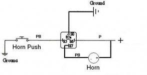
Purple = Power 12 VDC
Purple / Black switched goes to horn contact
 
my understanding is that there are 2 possibilities.

1. Is to use the purple power wire to power the relay switch and a fresh feed from the battery to power the horn.

2. What I think I'm going to do is to use the purple wire to wire the relay and the horn - with both then going to ground since the issue with the horns is not usually the deteriorated wire but the deteriorated horn switch.

others?
 
John-Peter that sounds logical but I'm not exactly clear how the relay gets wired to switch the Ground side of the circuit, not the 12VDC Side of the circuit. I know I need 12VDC and a Grounbd wire to power the relay. Do you need to wire it backwards with 12VDC going to the ground side of the relay in reverse of how it normally would be wired. Then the switched connection going to ground. I found this note which I think would apply hear.

Fiats through the mid seventies all use a three terminal horn relay, which is now long discontinued. The most common brand is Fiamm, though you'll also find Sipea or Mixo. Here's how the original relay works: Terminal 87 connects to the horn. Terminal 30 is the power supply from the battery. As you can see, it is bridged inside the case to provide power to the electromagnetic coil as well. Terminal 85 is connected to the horn button, which grounds at the steering wheel when depressed, thus completing the circuit and activating the electromagnetic coil in the relay, causing the points to close and the horn to blow.

I found this article re. wiring a horn relay for Fiats which ground through the horn contact button.
This is how you substitute a readily available four terminal relay in place of the three terminal relay:

Power lead to horn on terminal 87 as original

Power supply from battery on terminal 30 as original

Ground lead from horn button on terminal 85 as original

Connect a jumper wire from terminal 86 to terminal 30, thereby providing power for the electromagnetic coil.

Beep Beep-You're done!
 
Here's how it should work. I don't know the pin designations for the relay you are using, and I'm not sure of the wire color codes for your car. But you should be able to sort this out from the wiring diagram and the one below.

Sorry for the hand-drawn sketch; hope it's clear.
 
Steve, Standard Bosch Type relay Terminals marked 30, 85, 86, 87. As I see it, and my VOM says the same Purple Wire provides constant 12VDC, Horn Button Purple/Black shorts to ground and horn blows. So diagram on right looks like relay will be switching 12VDC + not the ground side of the circuit correct?

I need to interrupt the Purple /Black Ground Wire circuit that goes up to the horn button not switch the power wire going to the horn.
 
Try this:
 

Attachments

  • 12780.jpg
    12780.jpg
    9.2 KB · Views: 791
Chris,

That's exactly what I needed. Many thanks.
 
Pardon my slow uptake.
Horn terminal + usually gets P, still does but P also goes to 86 and 87. - on horn (usually gets PB) now goes to normal ground somewhere? Push horn, close relay, opens 12v to ground?

horn%20rela.jpg
 
yup - P powers horn and relay - however nothing happens in your diagram if you push the button - horn is not part of the circuit. P can hook up to 87 as per your diagram, but the horn needs to either be between P and 87 or between 30 and ground. - does that make sense?
 
So....
hornrelay.jpg
 
Actually something does happen. When you push the button, it actuates the relay by supplying a ground to its coil. This connects pin 87 to pin 30 and the jumper you show from P to 87 is directly shorted to ground through pin 30 and the relay fries. Also, if you do have a ground where your ?? are then the horn honks all the time. Remove the jumper you have between P and 87 and connect the horn, where the ?? are, to 87. Then, when you push the button, the relay actuates and supplies a ground for the horn through pins 87 to 30.

Oops, I see jvandyke slipped in while I was typing. I'm pretty slow at that. The jumper change he shows needs to go to the - side of the horn, not the + side. I believe the PB wire was initially connected there. Anyway, the one that does NOT have the P wire. Again that would kill the relay. The horn should NOT be grounded directly as it would honk all the time.
 

Attachments

  • 15774.jpg
    15774.jpg
    9.6 KB · Views: 706
:iagree:
 
Well, I've got more head scratch'n to do. PO put on a horn that grounds through its mount, I need new horn or inventive wiring.
 
not sure what you mean - can you post a diagram?
 
Horn has one terminal and the other side of the circuit is grounded through the horn's nut. I tested it. + to terminal, - touching various places, the threaded rod sets it off, can't very easily isolate that. Easy fix I guess is get a horn with two terminals, that doesn't rely on its mount for a ground.
horn.JPG
 
jvandyke said:
Well, I've got more head scratch'n to do. PO put on a horn that grounds through its mount, I need new horn or inventive wiring.

Doesn't matter where in the circuit the horn goes - as long as it is in the circuit. In other words, you can:

1. Put the horn between P and 87

OR

2. Between 30 and ground.

In other words, move the horn to the other side of the relay and let it ground through the nut
 
Okay, duh. Feeling pretty thick over here. The horn always being grounded dictates where it goes.
So, horn push grounds the relay, triggers a feed to the horn's + side, the horn already being ground, like anything else really.
Only difference here is instead of the switch (horn push in this case) sending 12v to the relay's trigger side, it grounds it. Same difference.
How's this looking?
hornrelayselfgrounding.jpg
 
Yes, and I think version 2 is fine. Mine runs purple to power and the horn & the relay. I then ran two wires off the solenoid for my headlights - one low and one high - one to each relay. Figured if one line burned, the other would get me home. I then put fuses between the relay and the actual - 4 fuses - 2 low/ 2 high.

Good luck!
 
:iagree: jvandyke's "or" diagram is your best solution, for the fuse reason he stated.
 
Just for posterity. Only those whose POs have installed non OEM, self grounding horns need to worry about this. Now I understand even more why he had a push button on the dash for the horn and never tackled the steering column/surround/slip ring set up. (Which I think I've sorted).
 
Back
Top