
-
 Hey Guest!
British Car Forum has been supporting enthusiasts for over 25 years by providing a great place to share our love for British cars. You can support our efforts by upgrading your membership for less than the dues of most car clubs. There are some perks with a member upgrade!**Upgrade Now**
(PS: Upgraded members don't see this banner, nor will you see the Google ads that appear on the site.)

Tips
- We have a special forum called "Member Articles" where you can submit actual articles for consideration for publication. Learn More
- Don't have an Avatar? If not, your avatar will default to the 1st character in your username. Go into "Account Details" to change your Avatar.
- Some basic forum navigation info: click
 Hey - did you know if you click on the title of a thread it will take you to the first unread post since you last visited that thread?
- Hey Guest - Is your British Car Club in our Clubs database? If not, send me a PM - Basil

- Looking for a local club? Click the "Clubs" tab above and browse hundreds of clubs world-wide.
- Add Android or iPhone APP: click
- Did you know - any picture or video you add in your posts in any marque-specific forum will also get added to the Media Gallery automatically.
- A few more tips about posting and replying: click
- Hey there Guest - be sure to keep your profile page up to date with interesting info about yourself: learn more
- More tips and tricks on Posting and Replying: click
 but were afraid to ask:
  STOP!! Never post your email address in open forums. Bots can "harvest" your email! If you must share your email use a Private Message or use the
  smilie in place of the real @
- Want to mention another member in a post & get their attention? WATCH THIS

- So, you created a "Group" here at BCF and would like to invite other members to join? Watch this!
- Hey Guest - A post a day keeps Basil from visiting you in the small hours and putting a bat up your nightdress!
- Hey Guest - do you know of an upcoming British car event?
 Pretty Please - add it to our Events forum(s) and add to the calendar! >> Here's How <<
- Hey Guest - you be stylin' Change the look and feel of the forum to fit your taste. Check it out
- If you run across an inappropriate post, for example a post that breaks our rules or looks like it might be spam, you can report the post to the moderators: Learn More
- If you would like to try some different "looks" or styles for the site, scroll to the very bottom, on the left and click the Style Selector.
You are using an out of date browser. It may not display this or other websites correctly.
You should upgrade or use an alternative browser.
You should upgrade or use an alternative browser.
TR2/3/3A Here We Go!
- Thread starter CJD
- Start date
OP
CJD
Yoda
Offline
We are iced in here in Fort Worth, so I have a chance to update the OD reassembly. First of all, I will try not to duplicate what you can find in the Laycock manual or the Buckeye article listed above. I plan to provide pictures to those documents, as I personally found this stuff pretty cosmic when you don't have a photo as a frame of reference. The order I am assembling is straight out of the Laycock manual. So, here we go...
This is what an overdrive tranny looks like in pieces. Pretty overwhelming! Mine was so messy that it was impossible to keep parts separated into their locations in the box. Fortunately, most of the parts are completely unique, so no chance of mixing them up...with one exception. Those are the thrust washers and shims. I recommend keeping the tranny parts away from the OD parts. If you do that part ID is easy.
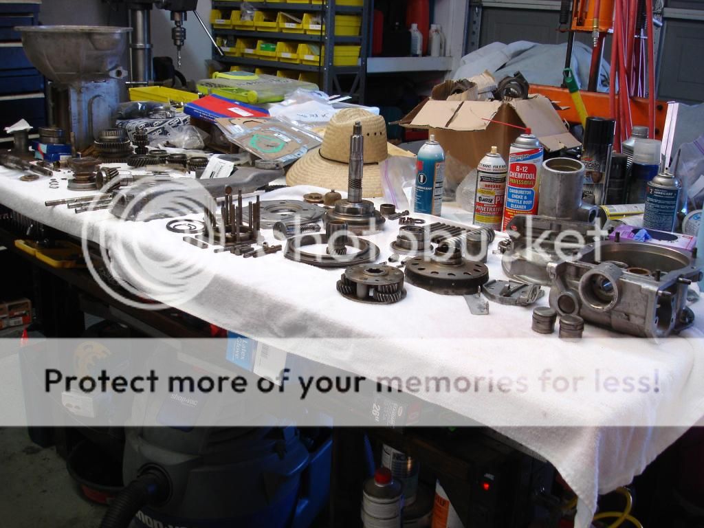
First of all, there are several gears and bushings in the OD that are splined and keyed onto the input shaft. The input shaft for the OD is the same shaft that comes out of the tranny. So...this means it is best to build the OD before you build the tranny, so you can use the shaft to align the gears and bushings. The alternative is to get a used OD shaft.
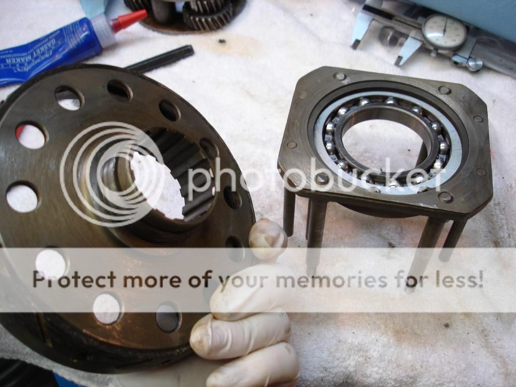
We start with the tail housing assembly. This assembly is comprised of the housing, the tail shaft, 2 bearings, and a shim.
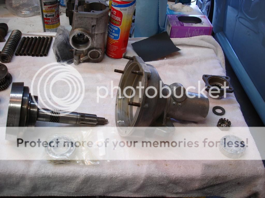
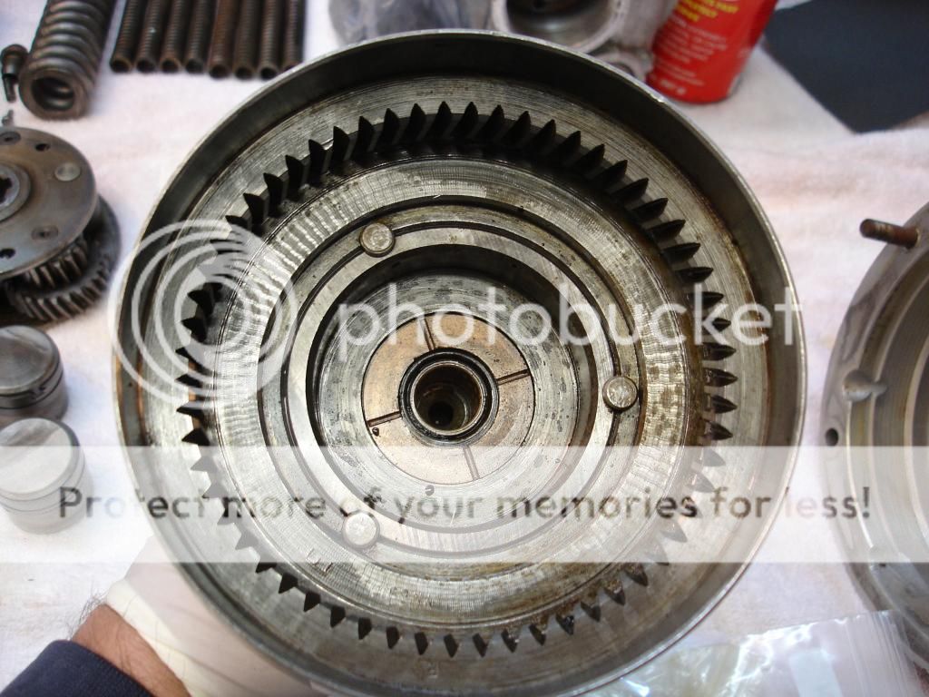
Now, in the manual the tail shaft is referred to as the "annulus". They are attached and are the same part. The anulus gets its name from the fact it has the large outer ring gear in it for the sun and planet gears. The outside of the anulus also has a cone shaped surface for the clutch drum to engage...but more on that later. I'm not going to go into how the gears work...just how they go together.
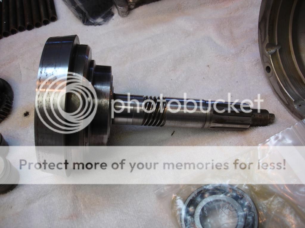
First step, the front gear goes on the tail shaft, and I used a press to drive it down against the annulus.
Now, the outer race of that bearing is driven into the front of the tailhousing. This is also a press fit, so a press is necessary. Hammering will destroy the bearing balls and races. Something to point out, I am using brand new bearings for the entire tranny. Not the bushes, but the ball bearings. No matter how much I tried to get the originalls turning freely, whenever I let them sit the black goo would bind them. I did not want to risk bearing failure.
This is what an overdrive tranny looks like in pieces. Pretty overwhelming! Mine was so messy that it was impossible to keep parts separated into their locations in the box. Fortunately, most of the parts are completely unique, so no chance of mixing them up...with one exception. Those are the thrust washers and shims. I recommend keeping the tranny parts away from the OD parts. If you do that part ID is easy.

First of all, there are several gears and bushings in the OD that are splined and keyed onto the input shaft. The input shaft for the OD is the same shaft that comes out of the tranny. So...this means it is best to build the OD before you build the tranny, so you can use the shaft to align the gears and bushings. The alternative is to get a used OD shaft.
We start with the tail housing assembly. This assembly is comprised of the housing, the tail shaft, 2 bearings, and a shim.

Now, in the manual the tail shaft is referred to as the "annulus". They are attached and are the same part. The anulus gets its name from the fact it has the large outer ring gear in it for the sun and planet gears. The outside of the anulus also has a cone shaped surface for the clutch drum to engage...but more on that later. I'm not going to go into how the gears work...just how they go together.


First step, the front gear goes on the tail shaft, and I used a press to drive it down against the annulus.

Now, the outer race of that bearing is driven into the front of the tailhousing. This is also a press fit, so a press is necessary. Hammering will destroy the bearing balls and races. Something to point out, I am using brand new bearings for the entire tranny. Not the bushes, but the ball bearings. No matter how much I tried to get the originalls turning freely, whenever I let them sit the black goo would bind them. I did not want to risk bearing failure.

OP
CJD
Yoda
Offline
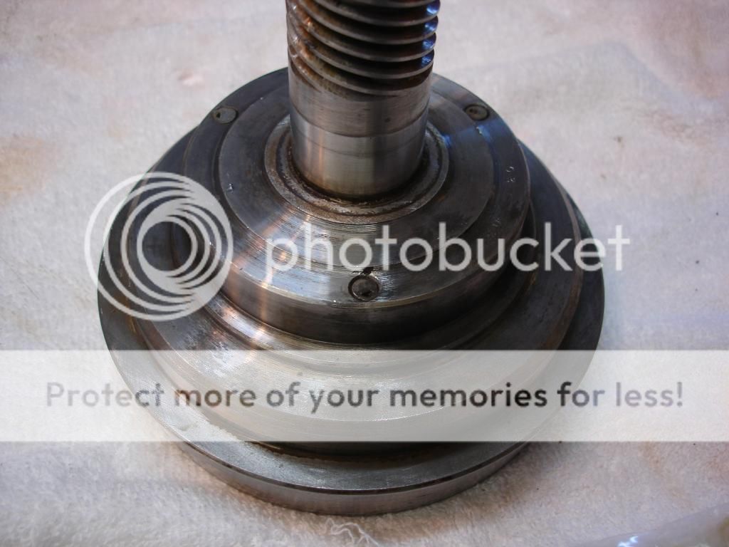
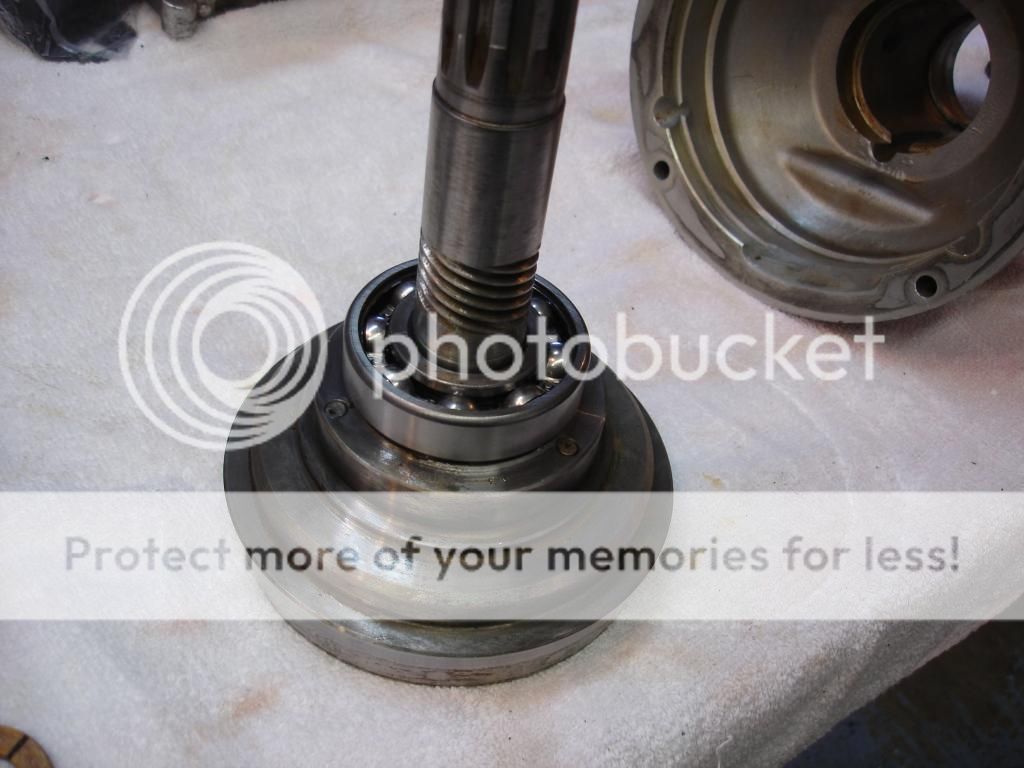
Now comes the shim washer onto the tail shaft, followed by the rear bearing. The bearing is driven down against the shim.
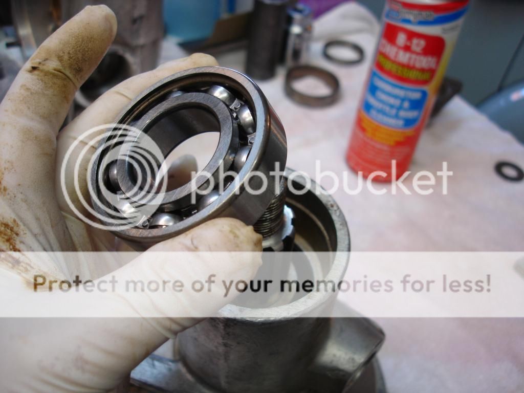
The next step is to check the free play of the bearings. Both the manual and the Buckeye article go into detail about how to do this. There is a problem with these descriptions, though. They would not work for me!
Here is the issue. Most ball bearings have some small amount of play when you move the inner and out races. The front bearing I got from Moss has no play. Normally you put the assembly together and check the play. Then you adjust the shim washer (available in many sizes...all for $20 per pop!!) to get the play in tolerance. Well...if the front bearing has no play, then you will always get "zero" play when checked. That was my issue. I finally went with precise measurements between the shaft, bearings, and case to ensure the tail bearing was as close as possible to the front bearing, without binding. This way, as the case heats and expands, the bearings will move apart and still not go into a bind.
Anyway...for checking the play, the drive shaft coupling goes on the tail shaft and gets torqued to spec. DO NOT install the rear seal for these checks.
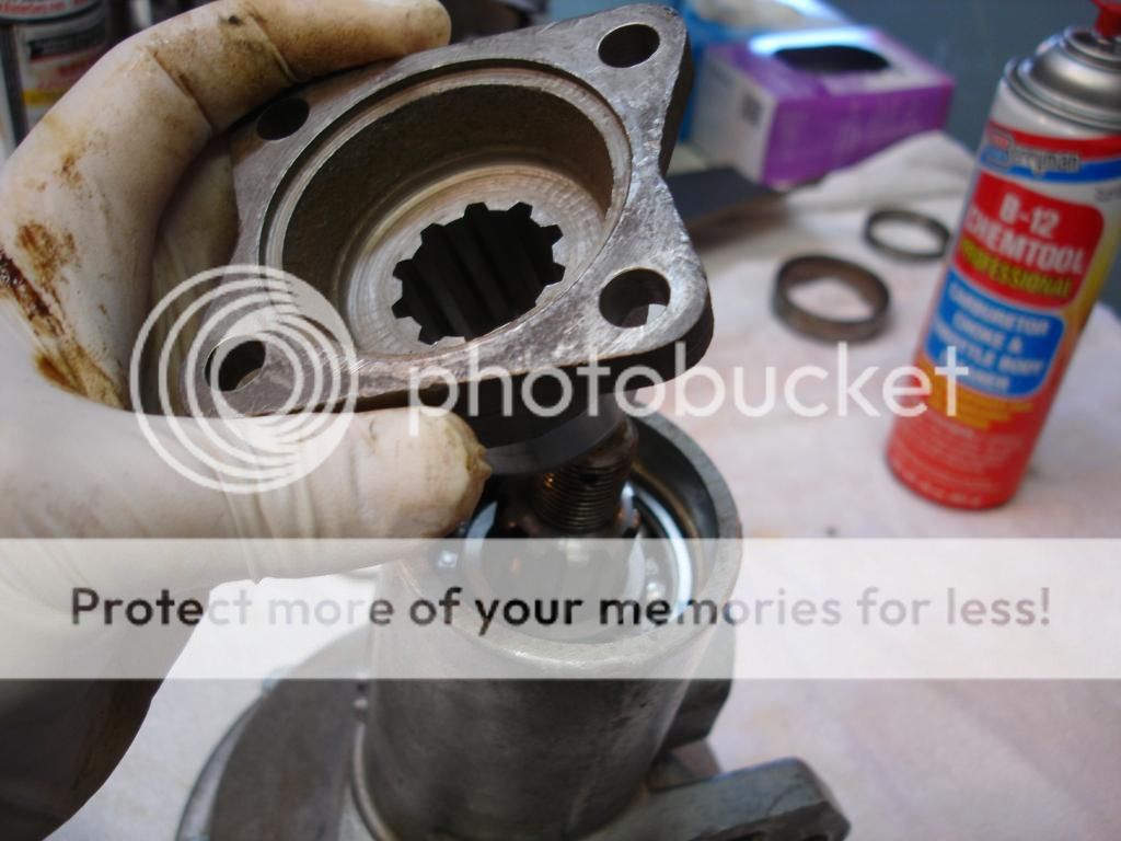
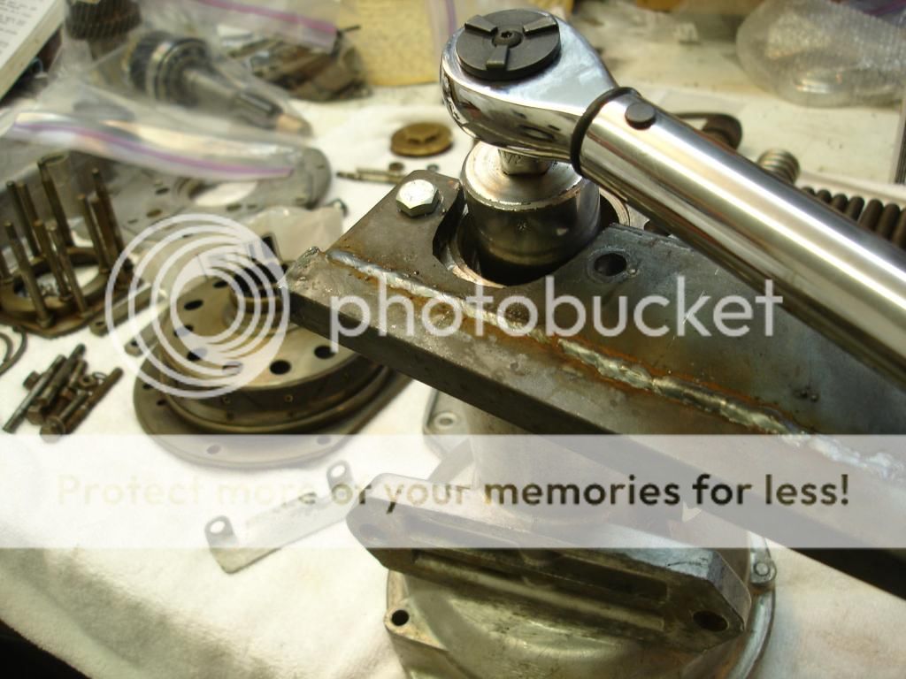
This is a puller that I used to remove the drive shaft flange between checks. You will need one like this or a press.
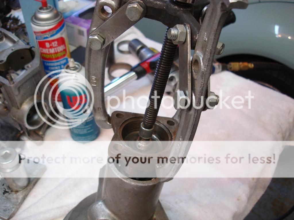
When you are happy with the bearing play, install the seal and install the drive flange for the final time...whew!
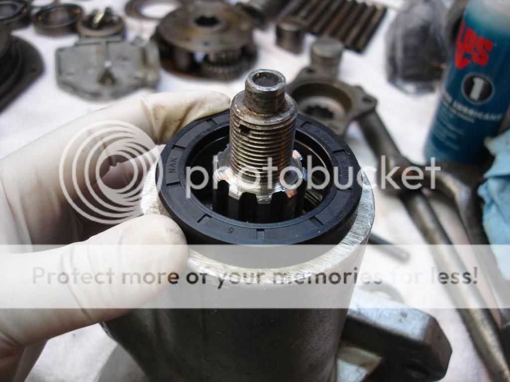
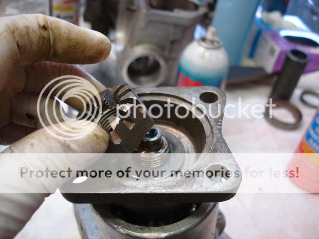
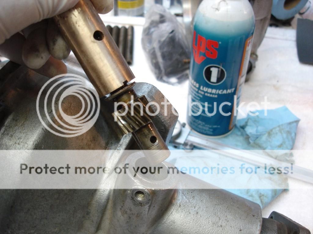
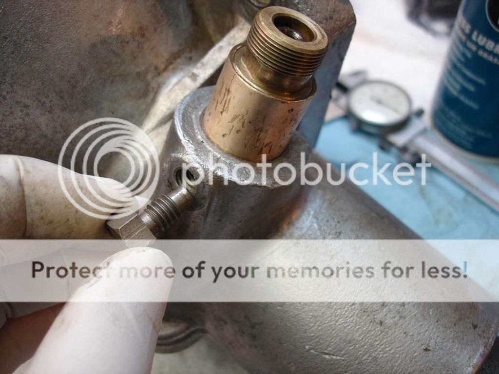
Now is a good time to install the speedo gear and bushing. I use a drop of loctite 518 on the threads of the set screw, since it passes through into the "wet" part of the OD.


The next step is to check the free play of the bearings. Both the manual and the Buckeye article go into detail about how to do this. There is a problem with these descriptions, though. They would not work for me!
Here is the issue. Most ball bearings have some small amount of play when you move the inner and out races. The front bearing I got from Moss has no play. Normally you put the assembly together and check the play. Then you adjust the shim washer (available in many sizes...all for $20 per pop!!) to get the play in tolerance. Well...if the front bearing has no play, then you will always get "zero" play when checked. That was my issue. I finally went with precise measurements between the shaft, bearings, and case to ensure the tail bearing was as close as possible to the front bearing, without binding. This way, as the case heats and expands, the bearings will move apart and still not go into a bind.
Anyway...for checking the play, the drive shaft coupling goes on the tail shaft and gets torqued to spec. DO NOT install the rear seal for these checks.


This is a puller that I used to remove the drive shaft flange between checks. You will need one like this or a press.

When you are happy with the bearing play, install the seal and install the drive flange for the final time...whew!

Now is a good time to install the speedo gear and bushing. I use a drop of loctite 518 on the threads of the set screw, since it passes through into the "wet" part of the OD.


OP
CJD
Yoda
Offline
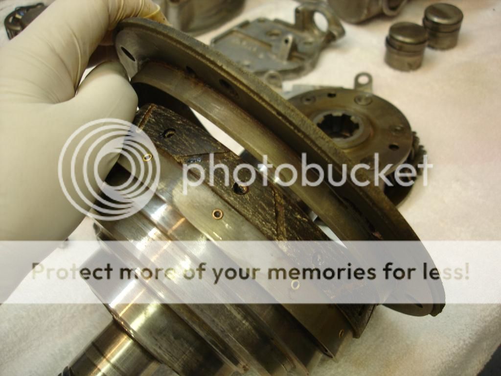
Now, the tail assembly gets mounted flange down in a vise. It will remain in this position for the remainder of the assembly.

Here is the first of many thrust washers. It goes into the center of the annulus.

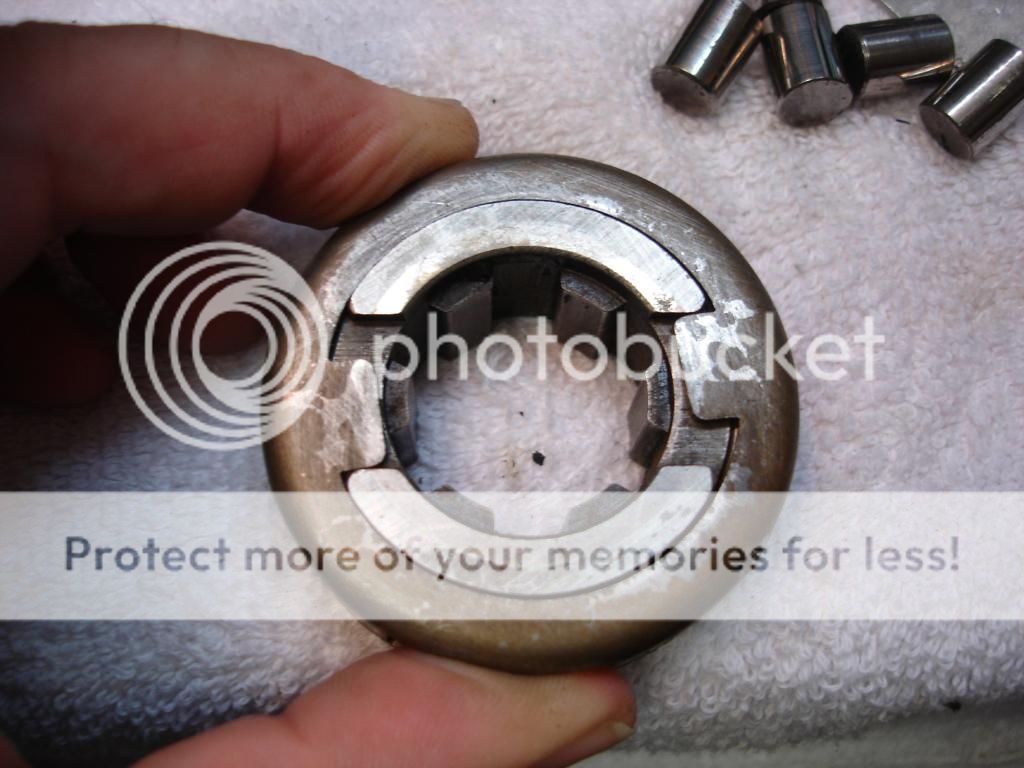
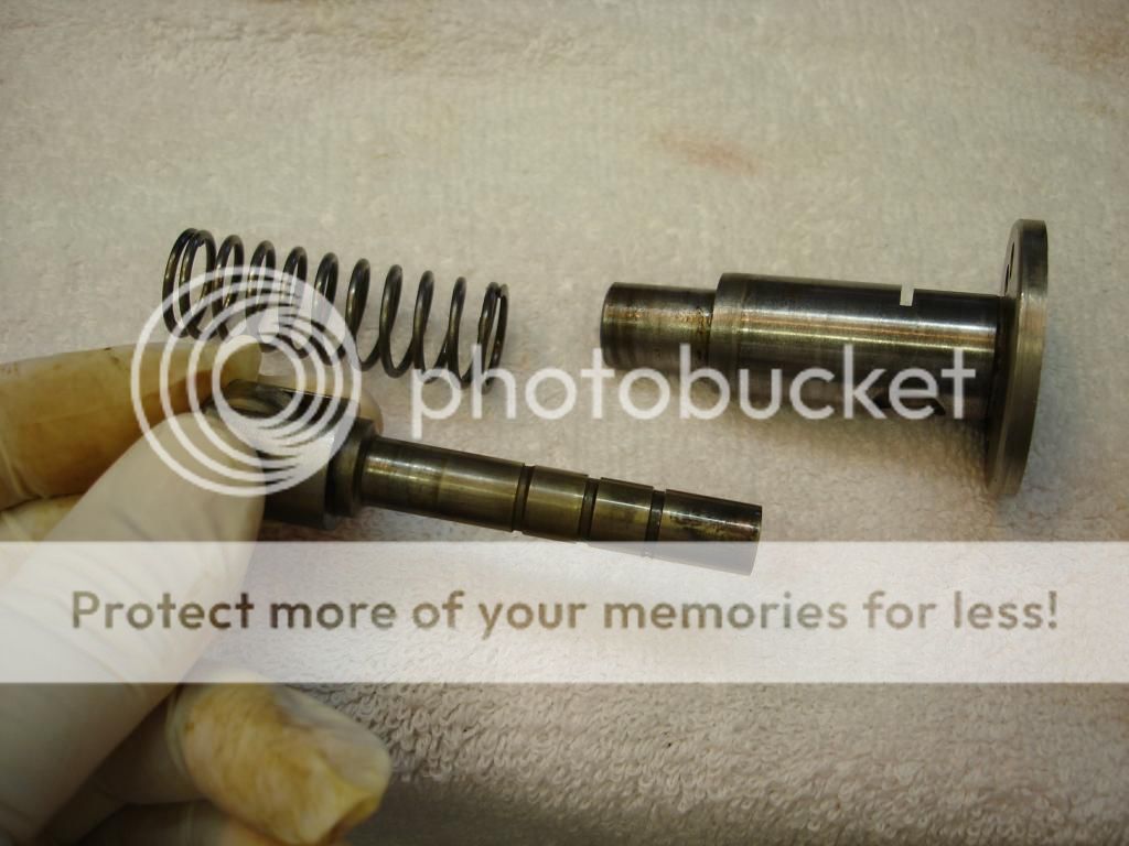
Now, we assemble the one way clutch. This is a very simple mechanism that works on the same principle as the old one speed bicycle brakes. It is a center cog wheel with tapered ramps. The cog is keyed to the shaft that comes out of the tranny. Rollers are spaced on the ramps and held in place by a cage retainer. A wire spring preloads the cage to press the rollers against the cog ramps. So, if the shaft turns one way, the rollers slide between the cog and the annulus. Turn the other direction and the cog ramps bind the rollers against the annulus, so the annulus must turn with the input shaft.
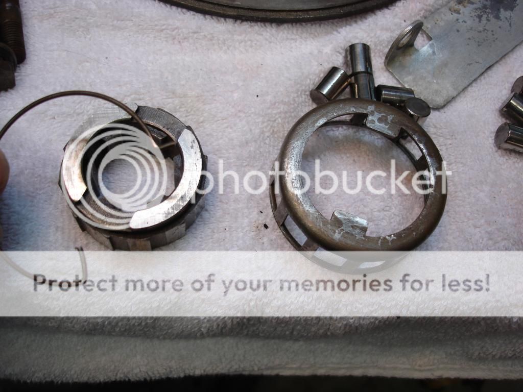
The wire sping fits into a hole in the cage, and the other end into a hole in the cog. It can fit in either direction, but this is how it should look to be correct.
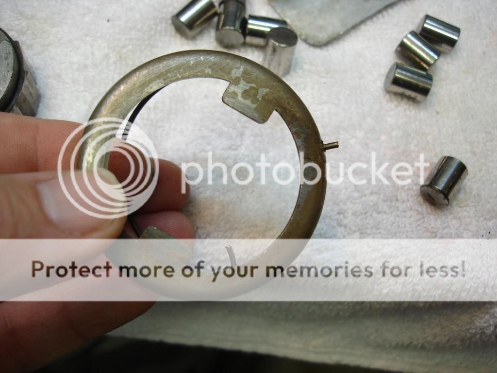
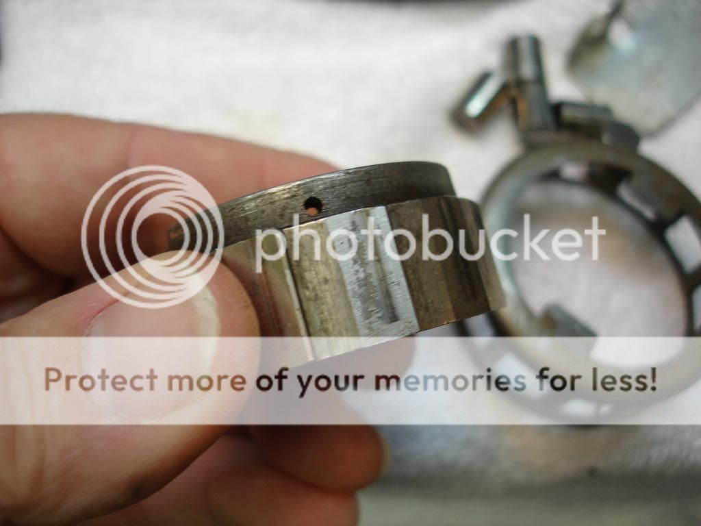
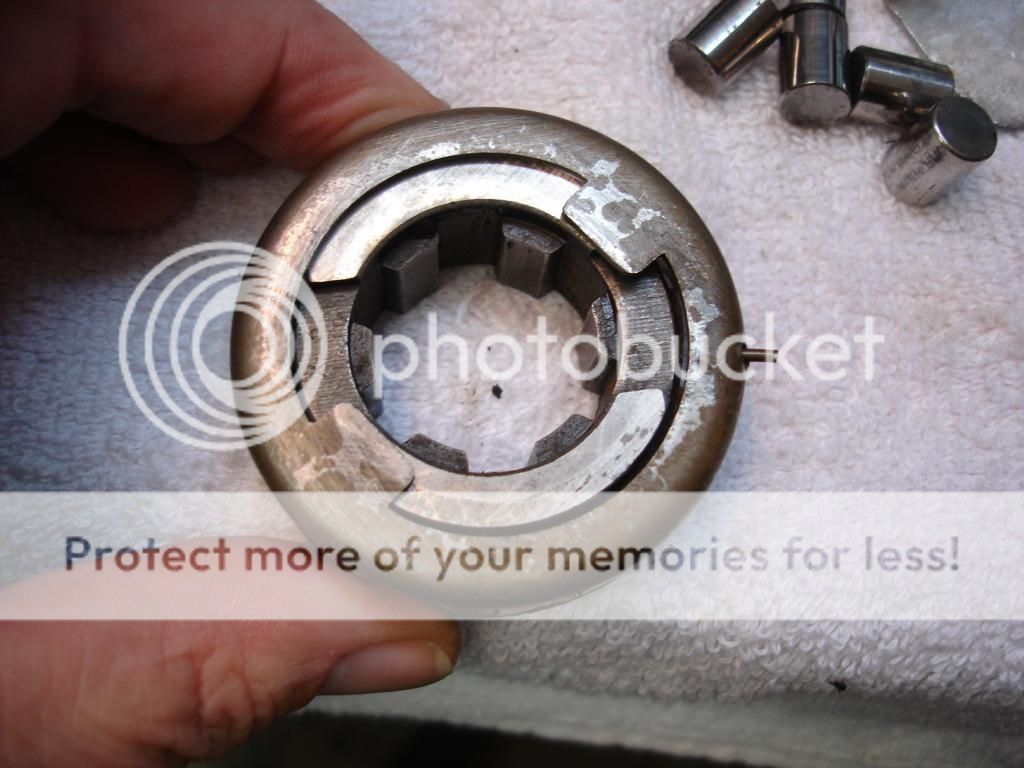
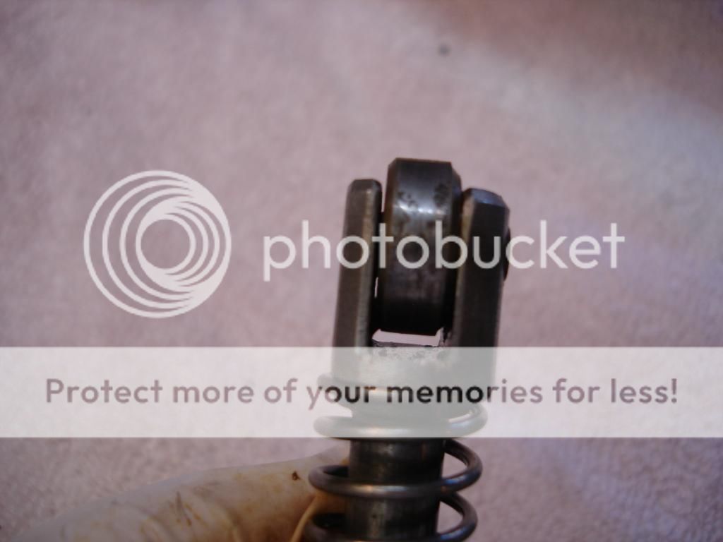
Once you have the cage and cog together with the spring wire, then you can give the cage a twist and it locks into a cutout in the cog, like so...
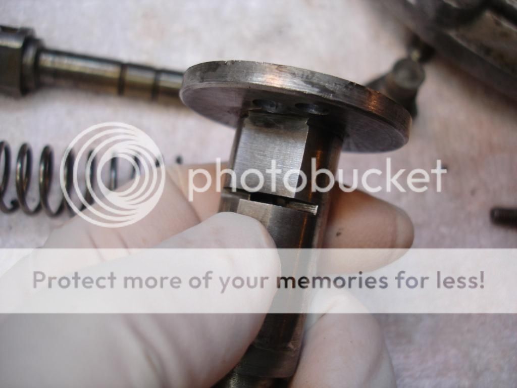
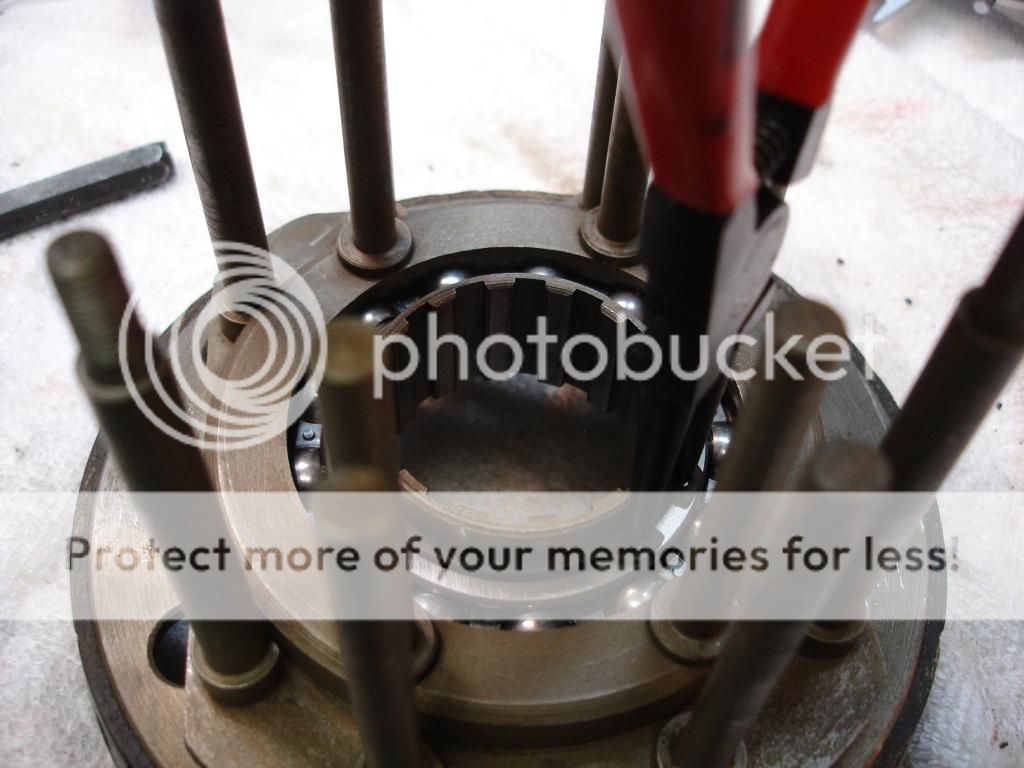
Now the next part, adding the rollers. Here is the issue...the cage is in a sprung position so the rollers are positioned "up" their ramps. If you tried to install the rollers and put the assembly inside the annulus, the rollers will be out to far to fit. The manual and the Buckeye article tell you to build a small jig to insert the balls. To complicated. I spun the cage and jammed a small nut into the keyway to lock it. Now the rollers can be installed "down" the cog ramps. I then used a tie wrap to hold them and shoved the assembly into the annulus.
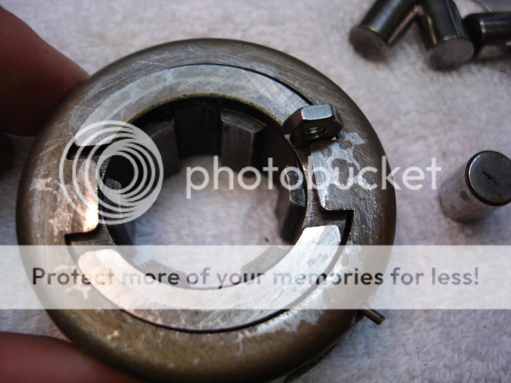
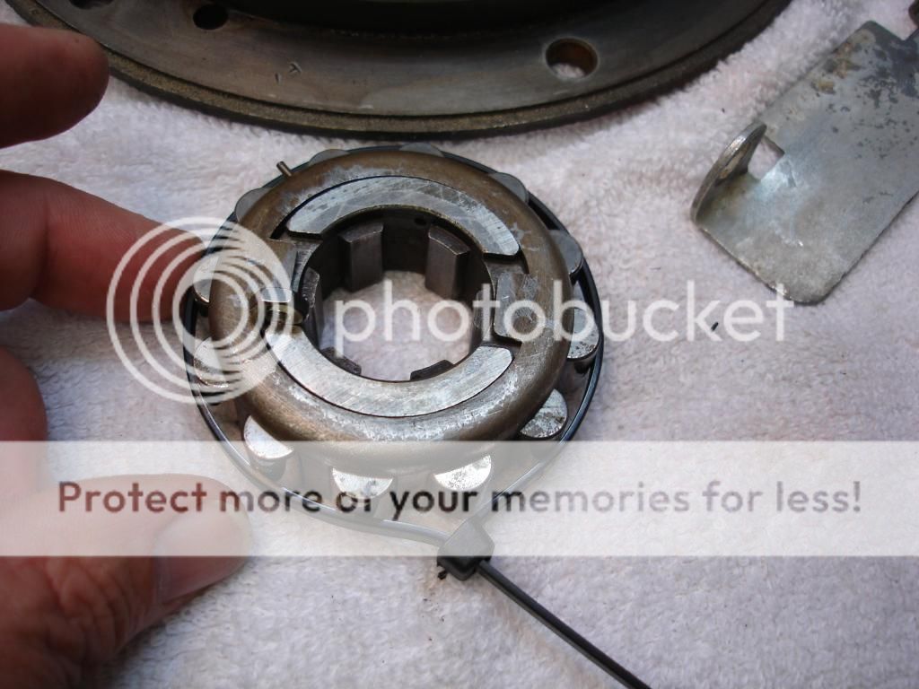
Of course, Important safety tip!, don't forget to remove the nut!
Now, let's talk a minute about the one way clutch we just assembled. As we mentioned, it keys to the tranny output shaft, and locks against the inside of the annulus, which is the tail shaft. It's purpose is to prevent the engine from revving wildly during the time it takes for the OD to engage and disengage. Without it, as the sliding clutch moves between direct drive and overdrive, the tranny shaft would have no load. This clutch locks the tranny output to the rear wheels. When the OD is locked in direct or OD mode, the one way clutch does nothing.
So to re-iterate, if your OD is stuck in OD mode, putting the car in reverse will attempt to turn the tranny shaft opposite the tail shaft, so the one way clutch will engage. The reverse gears will bind the clutch, and the clutch will destroy itself. So, on any OD car, if you doubt the car is out of OD, do not reverse! The corollary, if you ever start to reverse in an OD car and it feels like it's binding, don't rev and pop the clutch to get it going!

Here is the first of many thrust washers. It goes into the center of the annulus.

Now, we assemble the one way clutch. This is a very simple mechanism that works on the same principle as the old one speed bicycle brakes. It is a center cog wheel with tapered ramps. The cog is keyed to the shaft that comes out of the tranny. Rollers are spaced on the ramps and held in place by a cage retainer. A wire spring preloads the cage to press the rollers against the cog ramps. So, if the shaft turns one way, the rollers slide between the cog and the annulus. Turn the other direction and the cog ramps bind the rollers against the annulus, so the annulus must turn with the input shaft.

The wire sping fits into a hole in the cage, and the other end into a hole in the cog. It can fit in either direction, but this is how it should look to be correct.


Once you have the cage and cog together with the spring wire, then you can give the cage a twist and it locks into a cutout in the cog, like so...

Now the next part, adding the rollers. Here is the issue...the cage is in a sprung position so the rollers are positioned "up" their ramps. If you tried to install the rollers and put the assembly inside the annulus, the rollers will be out to far to fit. The manual and the Buckeye article tell you to build a small jig to insert the balls. To complicated. I spun the cage and jammed a small nut into the keyway to lock it. Now the rollers can be installed "down" the cog ramps. I then used a tie wrap to hold them and shoved the assembly into the annulus.


Of course, Important safety tip!, don't forget to remove the nut!
Now, let's talk a minute about the one way clutch we just assembled. As we mentioned, it keys to the tranny output shaft, and locks against the inside of the annulus, which is the tail shaft. It's purpose is to prevent the engine from revving wildly during the time it takes for the OD to engage and disengage. Without it, as the sliding clutch moves between direct drive and overdrive, the tranny shaft would have no load. This clutch locks the tranny output to the rear wheels. When the OD is locked in direct or OD mode, the one way clutch does nothing.
So to re-iterate, if your OD is stuck in OD mode, putting the car in reverse will attempt to turn the tranny shaft opposite the tail shaft, so the one way clutch will engage. The reverse gears will bind the clutch, and the clutch will destroy itself. So, on any OD car, if you doubt the car is out of OD, do not reverse! The corollary, if you ever start to reverse in an OD car and it feels like it's binding, don't rev and pop the clutch to get it going!
OP
CJD
Yoda
Offline
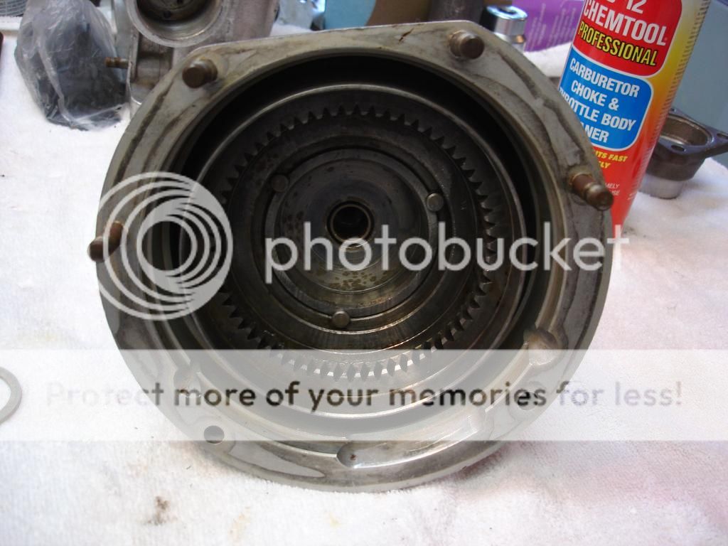
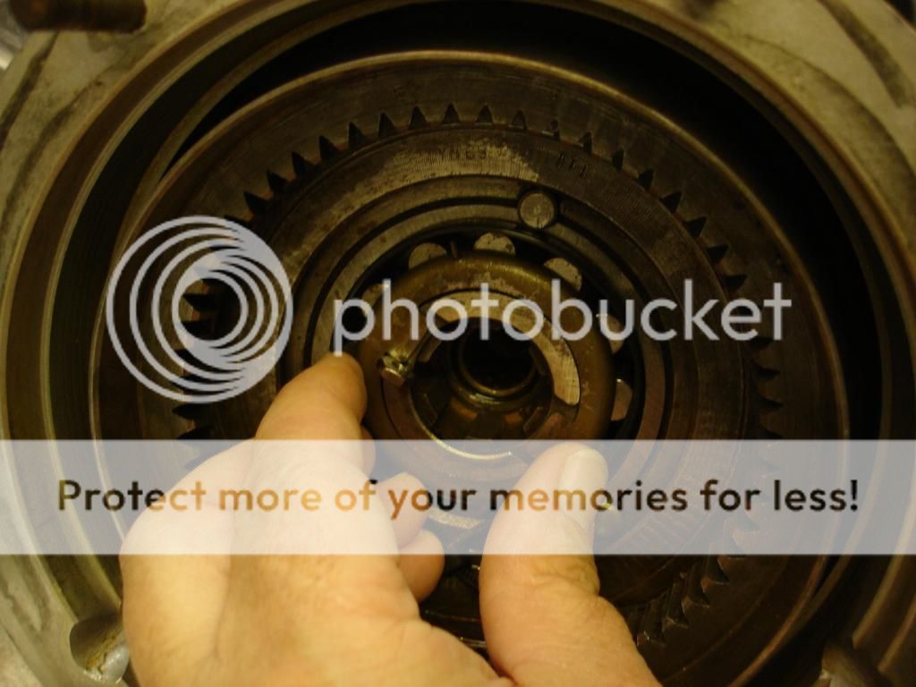
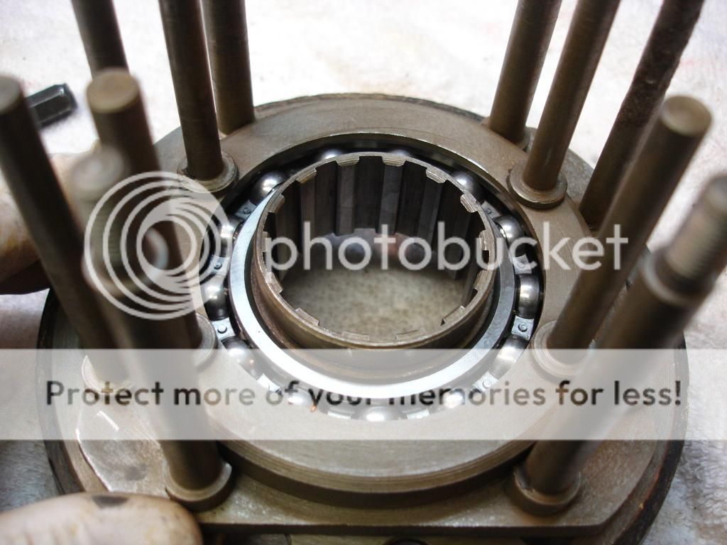
At this point, you are done with the tail housing assembly. Install the tranny output shaft and make sure the cog and thrust washer are aligned. Installed, you can make sure the one way clutch is in correctly, as the shaft will turn the tail shaft clockwise, but not counterclockwise.
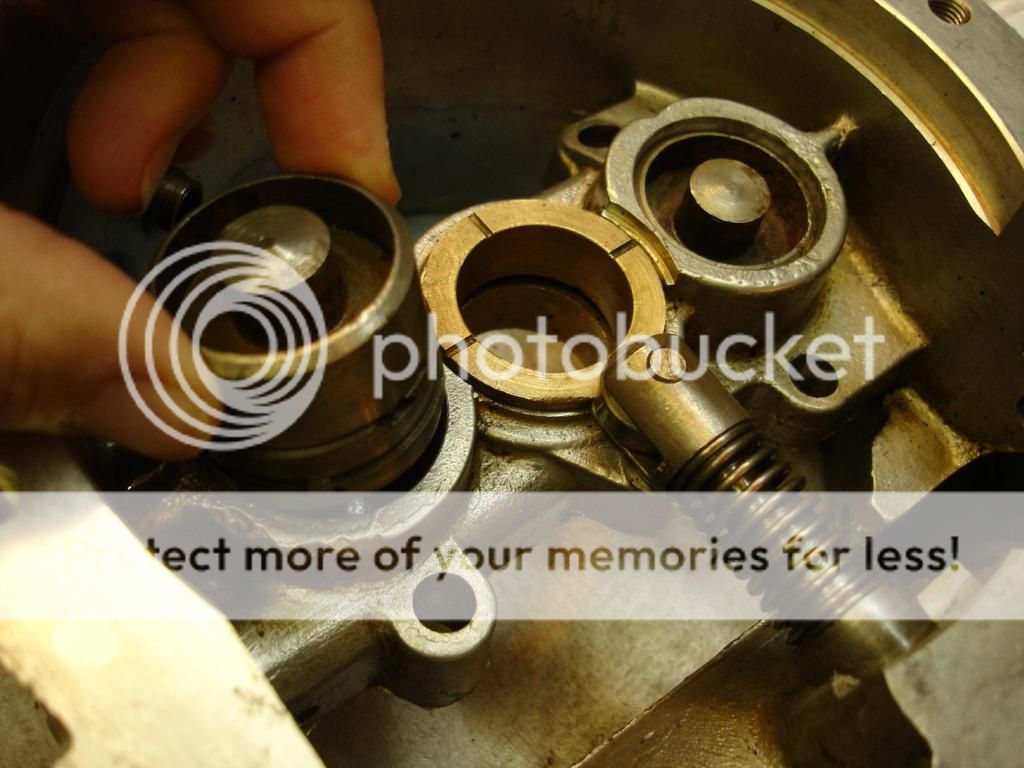
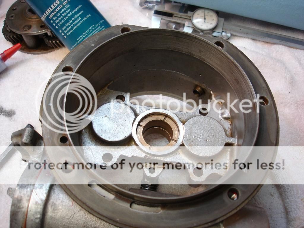
Now we move to the "main casing" assembly. This is where the main inter workings are located. I thought I had the case thoroughly cleaned. I was wrong. When I set the casing aside for a couple weeks, the black goo continued to ooze from passageways that I didn't even know existed!
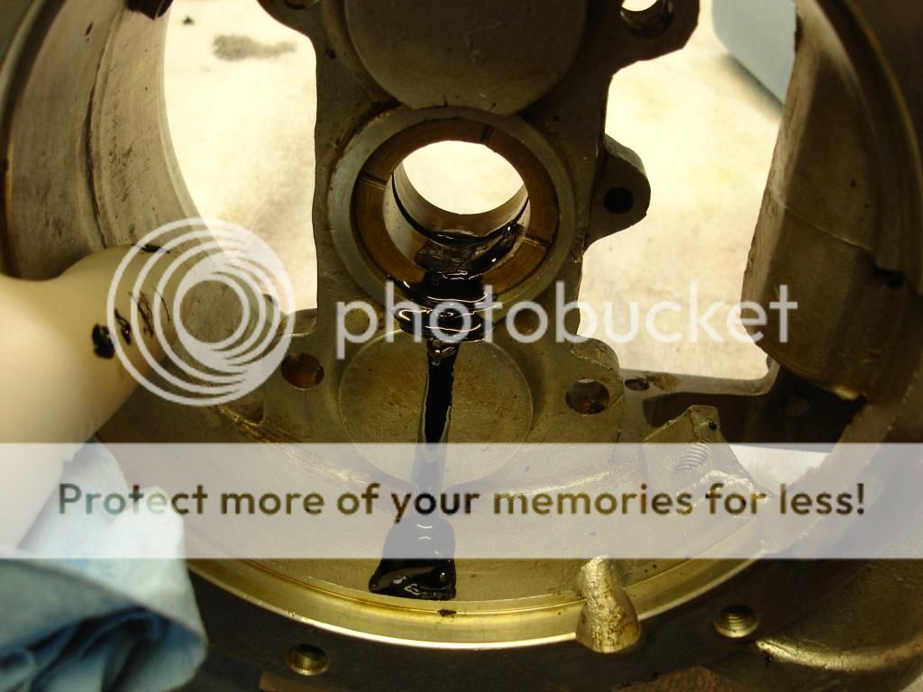
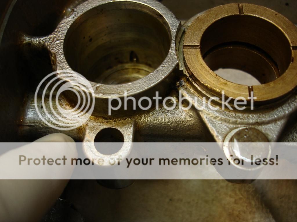
Of note, the bronze bearing shown in the above pic is the center bearing. If you note, it has a groove in the center. The OD is pressure oiled...pretty cool! The way it works is that the pump pressurizes the accumulator. When the accumulator piston moves back far enough, it vents any extra oil from the pump into a passageway...which eventually leads to this central bearing. Then the tranny shaft has a drilled hole that receives the overflow oil and allows it to pass inside the shaft. From there, every bush and bearing gets a drilling to receive the oil...all the way back to the one way clutch we just assembled. Pretty cool! But also a lot of passageways for my black goo to hide.
I finally heated the entire main casing so the goo would flow out. Then it was back to the solvent tank again. Bummer.
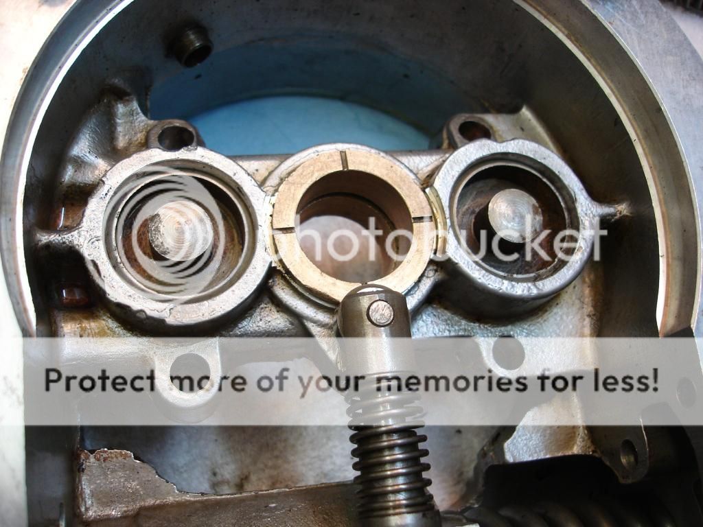
Here is a photo trail of the mainshaft oil pasages...
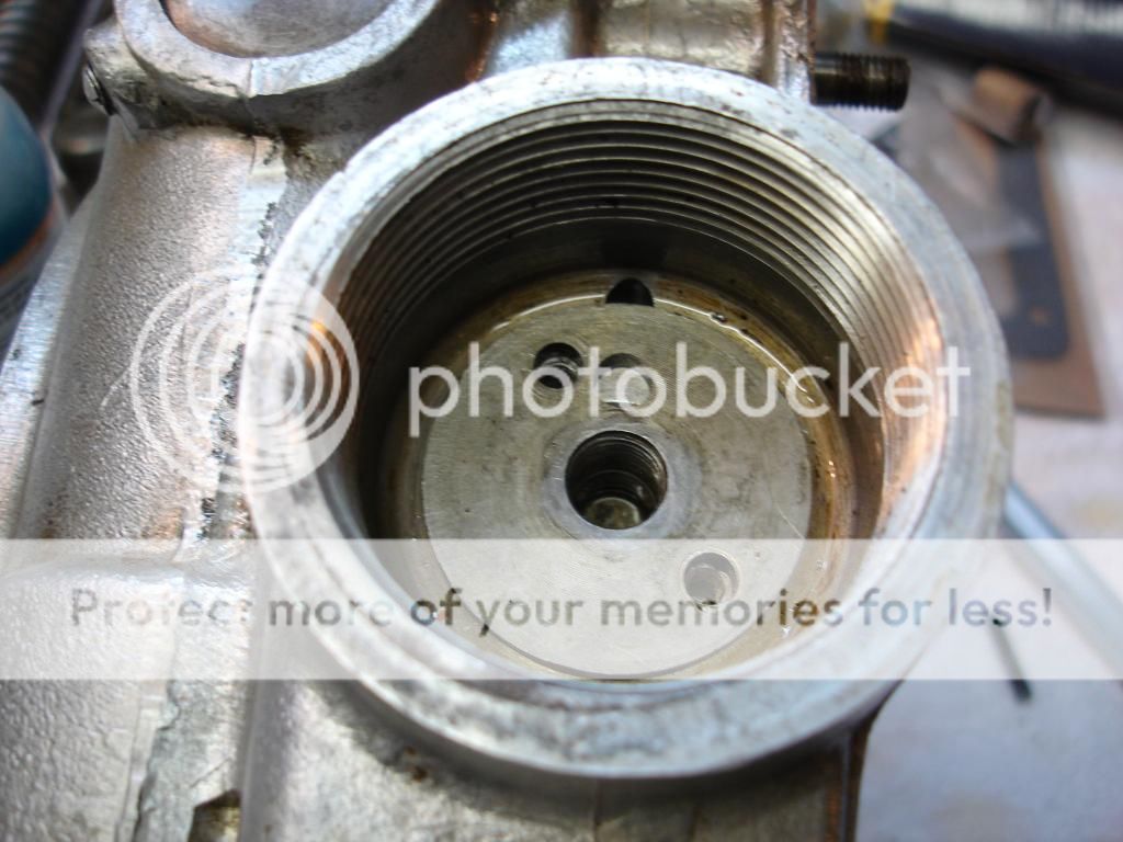
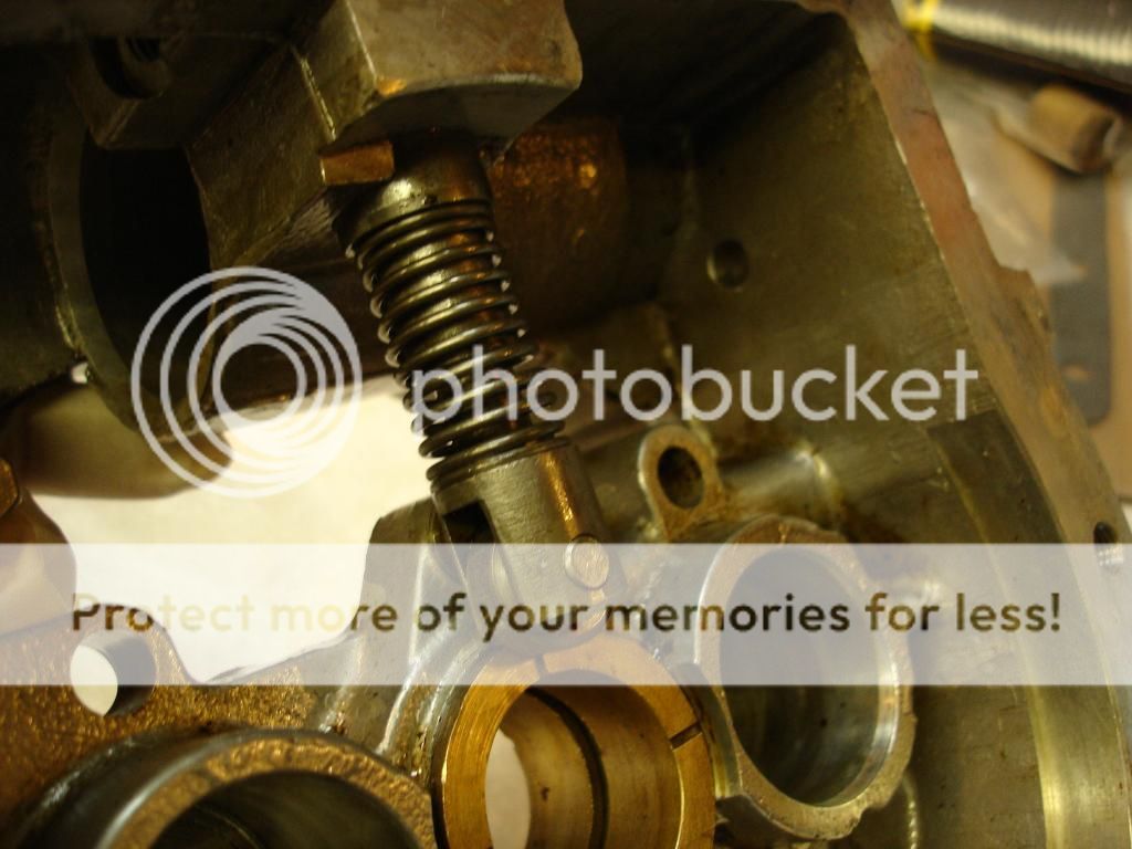
Here is the inside of the accumulator bore. There are holes about 3/4" up the bottom of the bore that relieve the extra oil to a passage in the casing.

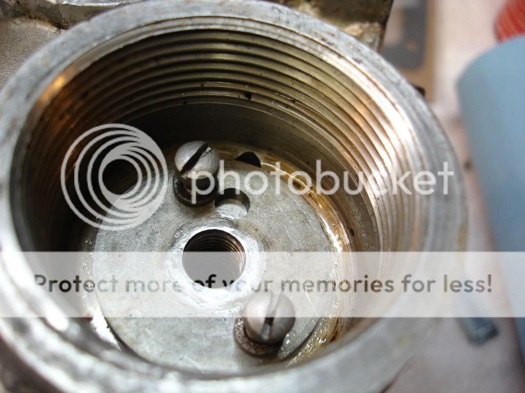
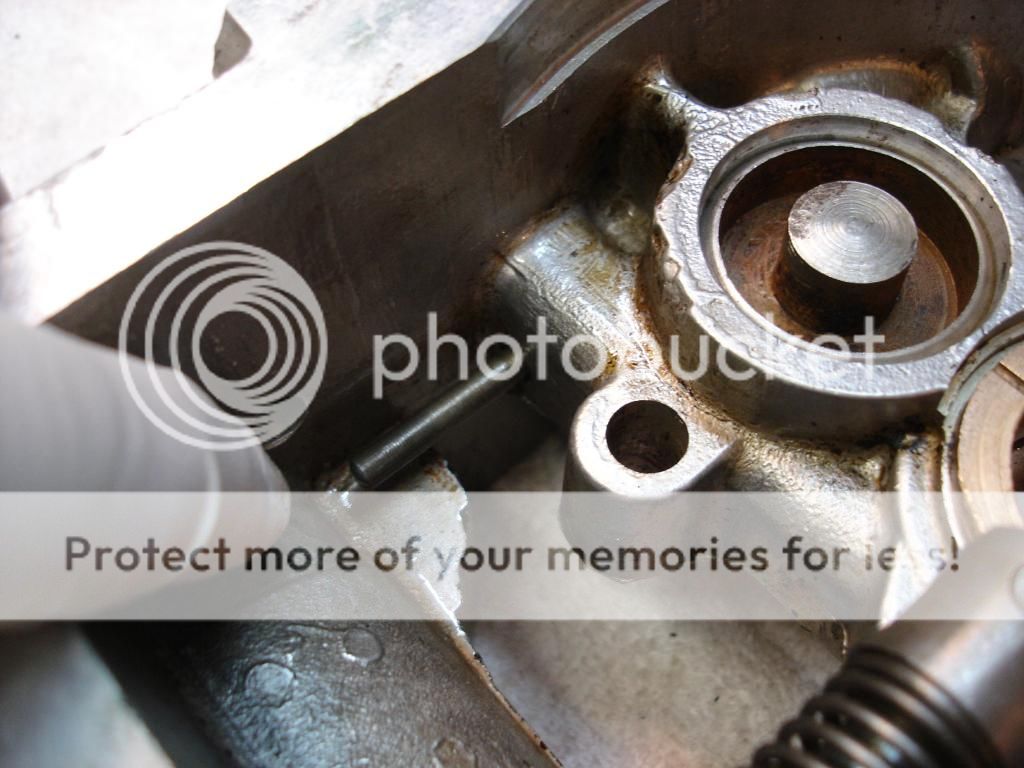
From the accumulator, it goes to a welch plug and through this passage...notice there are steel plugs that seal the passage following its drilling at the factory...
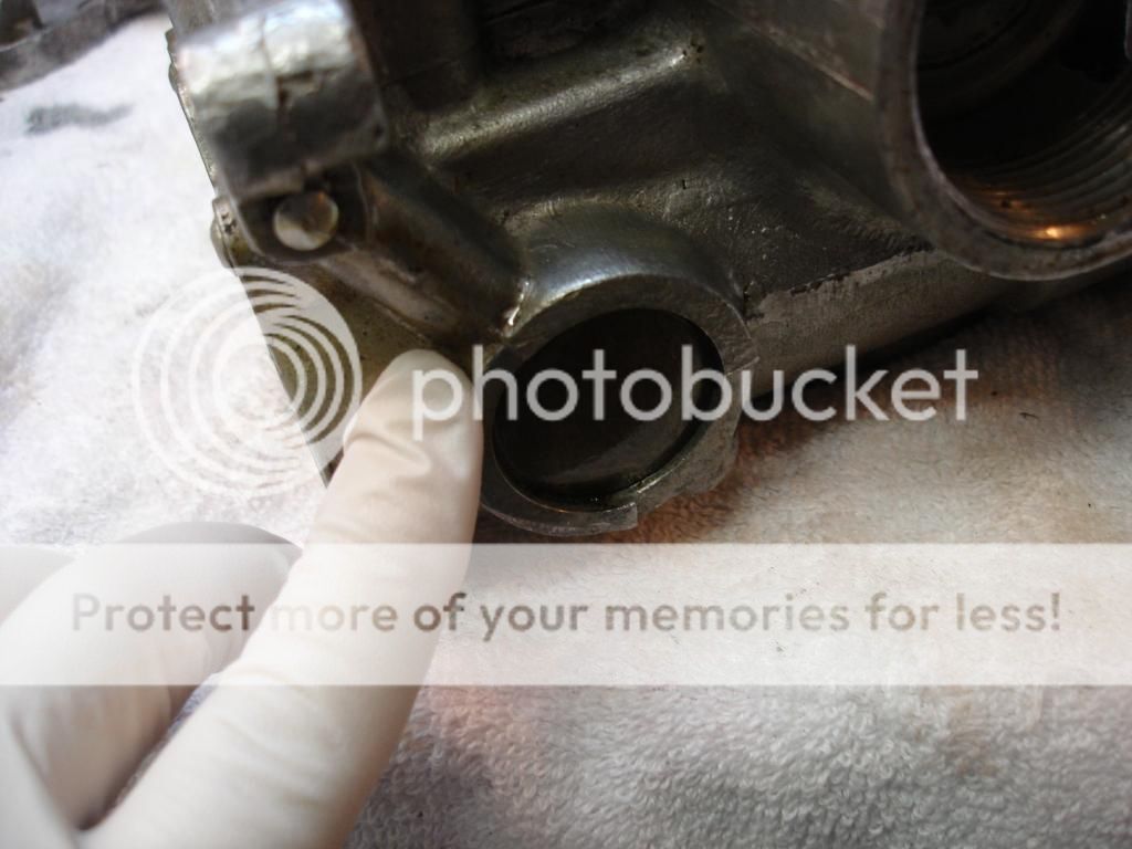
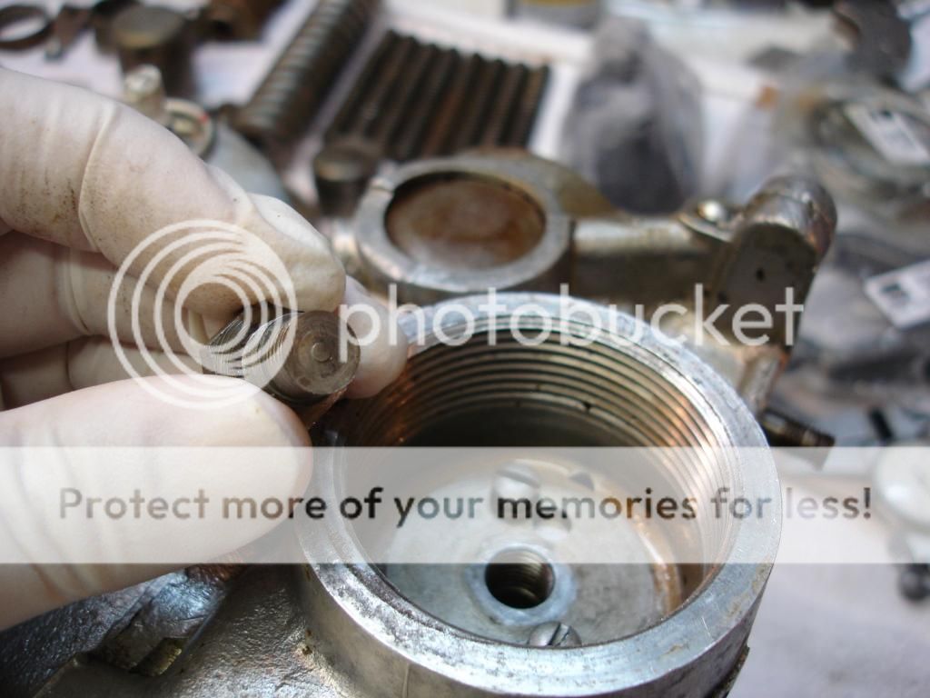
Now, it turns a corner and follows the outside of the case upward...
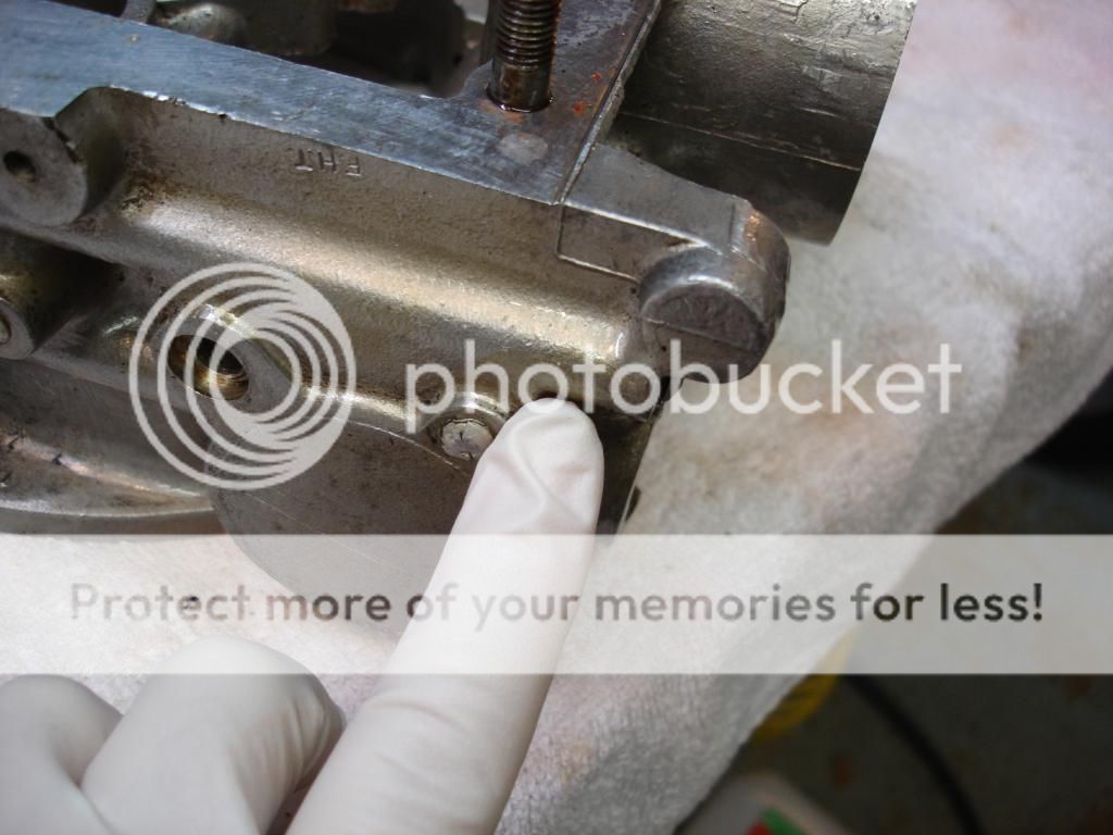
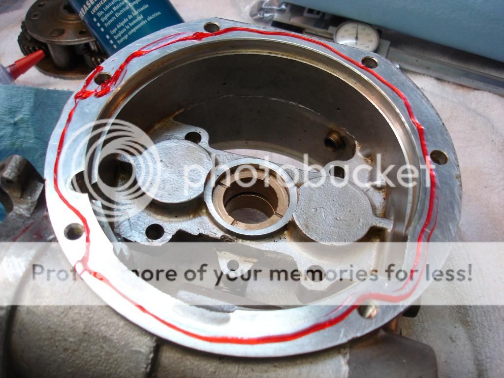
To here, where it turns another corner to go inside the case...

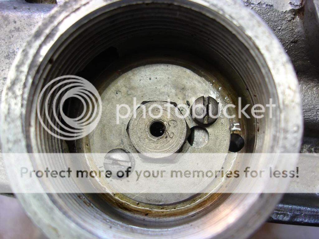
And finally through this drilling to the center bearing...
What a ride! And a lot of passages full of black goo...
Now we move to the "main casing" assembly. This is where the main inter workings are located. I thought I had the case thoroughly cleaned. I was wrong. When I set the casing aside for a couple weeks, the black goo continued to ooze from passageways that I didn't even know existed!

Of note, the bronze bearing shown in the above pic is the center bearing. If you note, it has a groove in the center. The OD is pressure oiled...pretty cool! The way it works is that the pump pressurizes the accumulator. When the accumulator piston moves back far enough, it vents any extra oil from the pump into a passageway...which eventually leads to this central bearing. Then the tranny shaft has a drilled hole that receives the overflow oil and allows it to pass inside the shaft. From there, every bush and bearing gets a drilling to receive the oil...all the way back to the one way clutch we just assembled. Pretty cool! But also a lot of passageways for my black goo to hide.
I finally heated the entire main casing so the goo would flow out. Then it was back to the solvent tank again. Bummer.
Here is a photo trail of the mainshaft oil pasages...
Here is the inside of the accumulator bore. There are holes about 3/4" up the bottom of the bore that relieve the extra oil to a passage in the casing.

From the accumulator, it goes to a welch plug and through this passage...notice there are steel plugs that seal the passage following its drilling at the factory...

Now, it turns a corner and follows the outside of the case upward...

To here, where it turns another corner to go inside the case...

And finally through this drilling to the center bearing...

What a ride! And a lot of passages full of black goo...
M_Pied_Lourd
Darth Vader
Offline
Very Nice John,
I appreciate you taking the time to document. This is something I have yet to do and it is great to have this as a reference for the future. I have bookmarked it and will continue to watch your progress.
Cheers
Tush
I appreciate you taking the time to document. This is something I have yet to do and it is great to have this as a reference for the future. I have bookmarked it and will continue to watch your progress.
Cheers
Tush
OP
CJD
Yoda
Offline
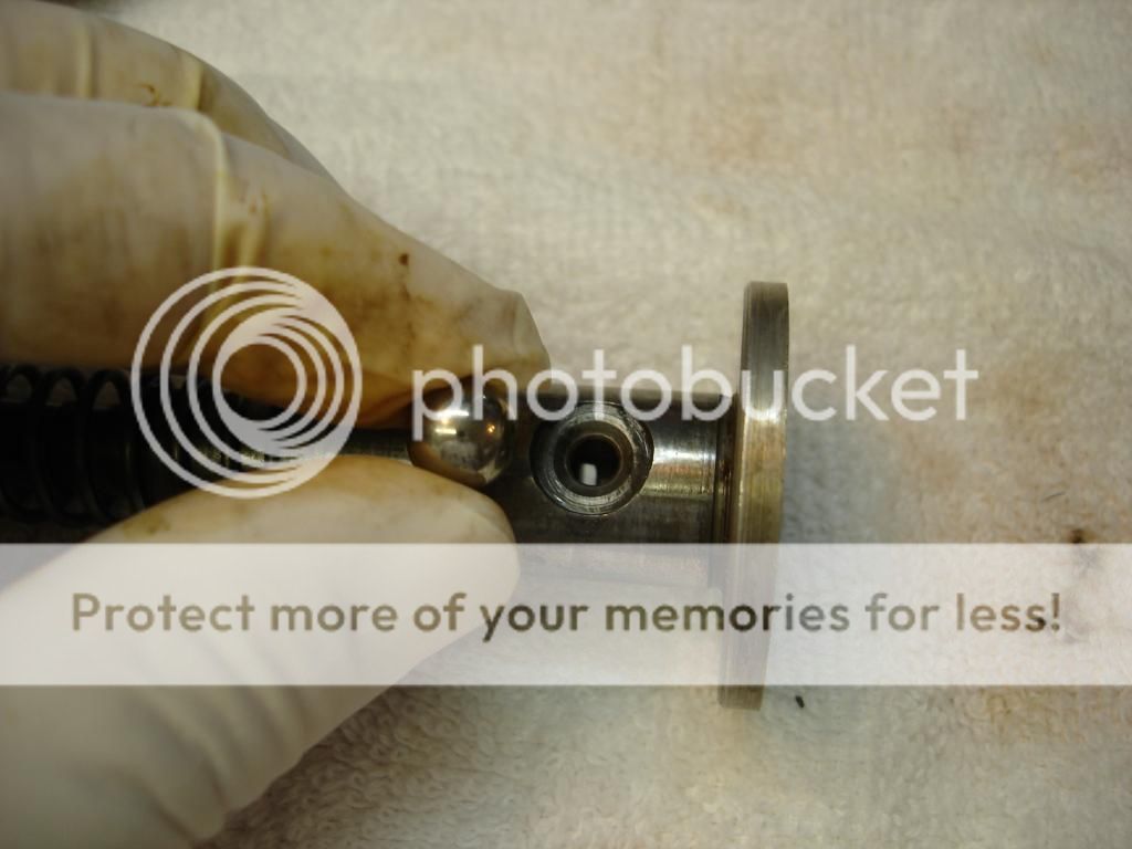
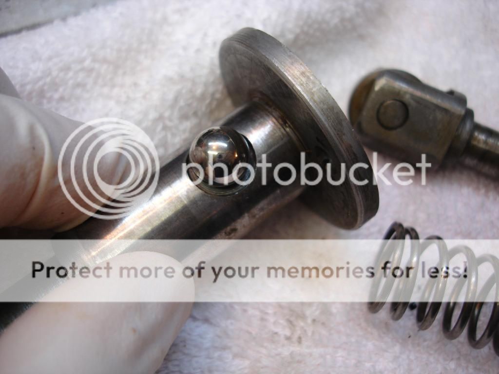
Next the pump. Very simple. A roller wheel on the end of the piston, a spring to return the piston upward, and a cylinder.
One side of the cylinder has a slit. This is where the oil enters the cylinder. No check valve. Just this...
This is a hole in the side of the cylinder, which is sealed by this ball. The ball is held by a spring, so it allows oil out of the cylinder, but not back into it.
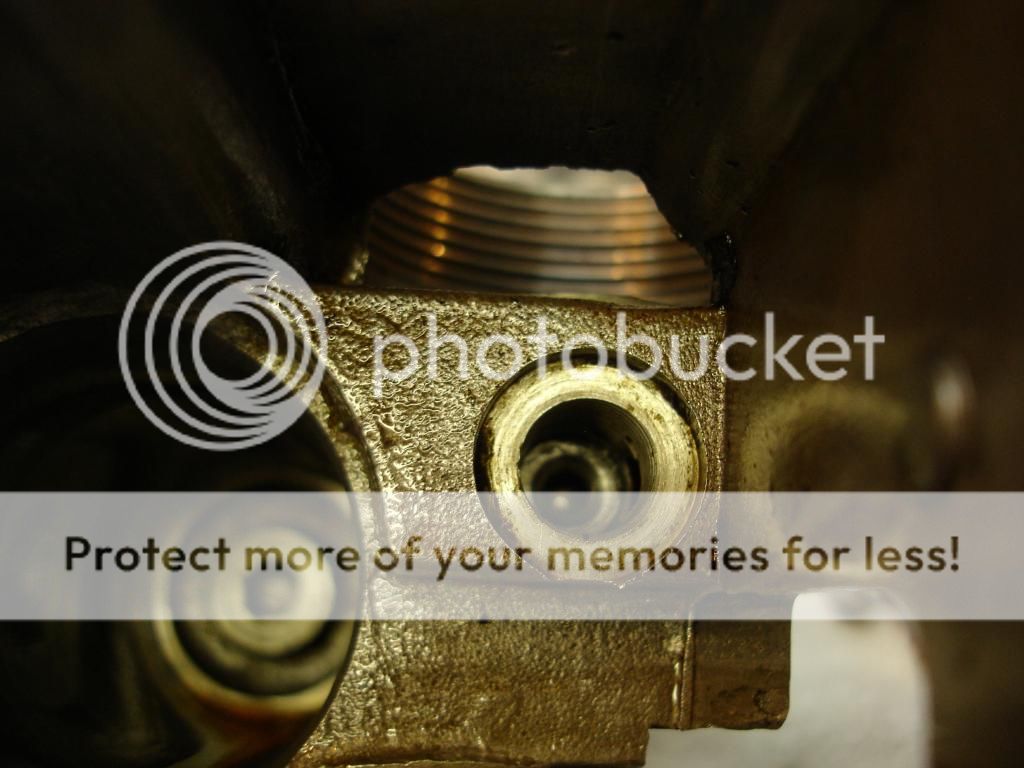
Here is the spring assembly which holds the ball against the pump cylinder. This plug is located inside the OD solenoid cover.

This is where it screws into the pump side. This view is looking inside the solenoid cover, right next to the accumulator bore.
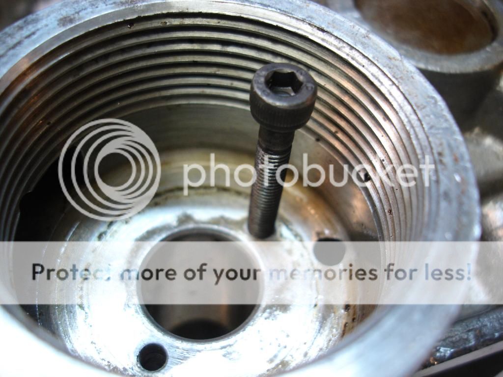
Because it is essential to get the ball lined up with the pump cylinder, and the cylinder is pressed into its bore, you must line it up with pins as it is pressed in. Here are home made pins I used...
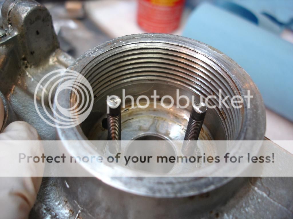
And, here is the pump pressed into place. The guide pins are removed and replaced by 2 slot head screws. And, finally, a plug is installed to seal the bottom of the cylinder.
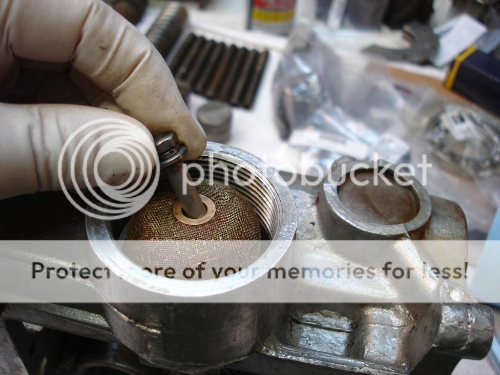
The hole in the plug does not go all the way through. It is threaded to hold the filter screen screw...(looks a lot better than in the picture in my first post!!
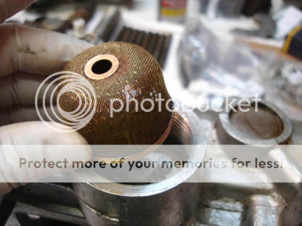
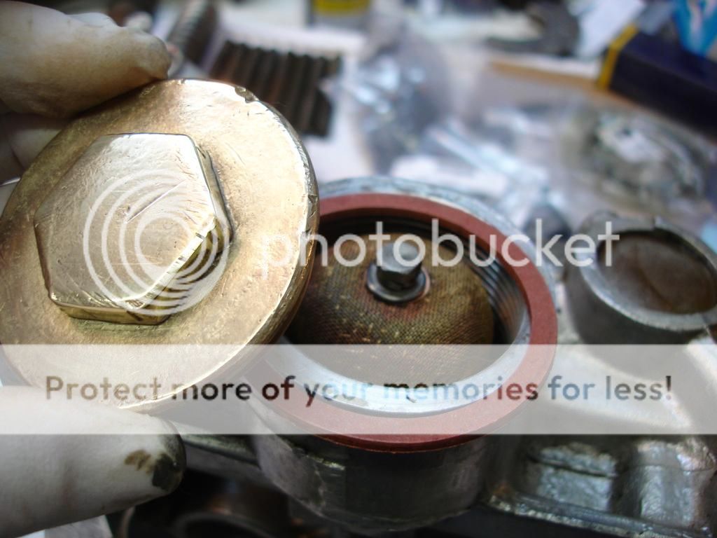
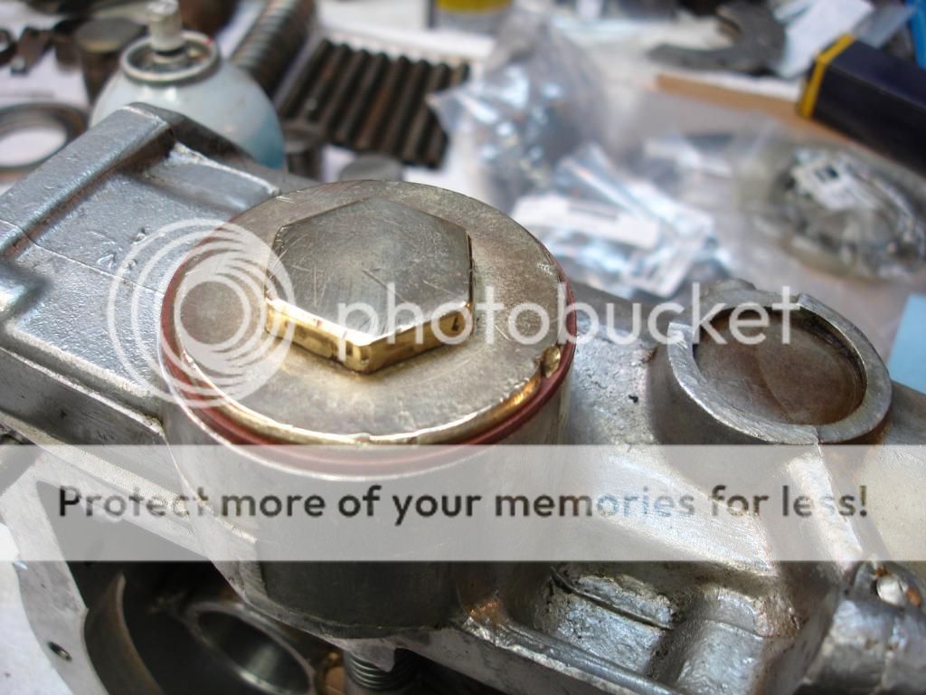
And, this all gets sealed with a new washer and the OD drain plug. This particular plug is made of unobtainium.
And this is the topside of the pump after it's pressed into the case.
Here is the cam that keys on the input shaft to operate the pump.


One side of the cylinder has a slit. This is where the oil enters the cylinder. No check valve. Just this...

This is a hole in the side of the cylinder, which is sealed by this ball. The ball is held by a spring, so it allows oil out of the cylinder, but not back into it.

Here is the spring assembly which holds the ball against the pump cylinder. This plug is located inside the OD solenoid cover.


This is where it screws into the pump side. This view is looking inside the solenoid cover, right next to the accumulator bore.

Because it is essential to get the ball lined up with the pump cylinder, and the cylinder is pressed into its bore, you must line it up with pins as it is pressed in. Here are home made pins I used...


And, here is the pump pressed into place. The guide pins are removed and replaced by 2 slot head screws. And, finally, a plug is installed to seal the bottom of the cylinder.


The hole in the plug does not go all the way through. It is threaded to hold the filter screen screw...(looks a lot better than in the picture in my first post!!


And, this all gets sealed with a new washer and the OD drain plug. This particular plug is made of unobtainium.


And this is the topside of the pump after it's pressed into the case.

Here is the cam that keys on the input shaft to operate the pump.

Last edited:
Dang this is fun to watch! I must confess the Liliputian in me keeps muttering "it'll never work" but that's just because if I was doing this I would find a way to bugger it up. There is a guy named Robert Jasper who rebuilt my tranny and overdrive and he has done many of these. A key part of his process is hooking it up to an engine after he is done but before it is installed. That way he can test all the systems and pressure requirements to make sure all is good. You obviously know what you are doing but you may want to chat with Bob for some tips.
Cheers
Dan
Cheers
Dan
OP
CJD
Yoda
Offline
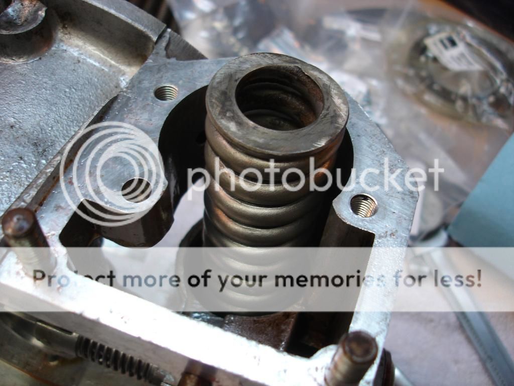
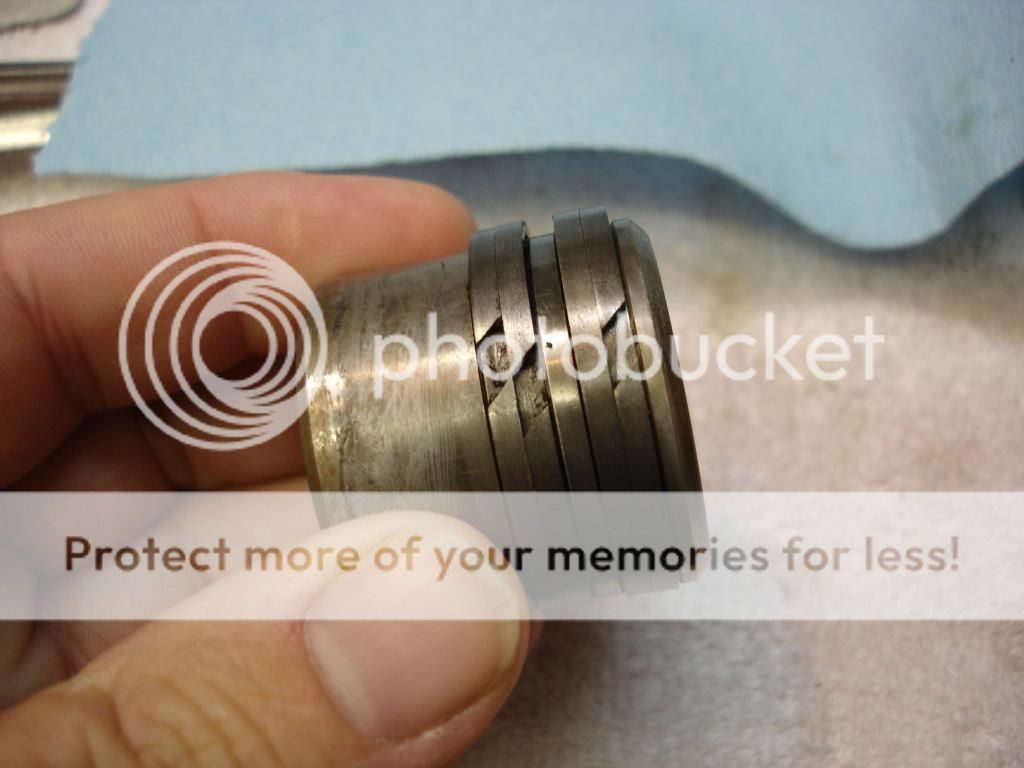
Next is the accumulator piston. This is the earlier, 1-1/8" accumulator. The new one has a housing that slips inside the casing. This early version just has the piston riding inside the aluminum casing bore. This pic shows the rings. They are very thin, like maybe .010" thick. There are actually 6 of them. 4 easily viewed from the outside, and 2 under those that push the outer rings even harder against the bore. In this pic the gaps are all lined up. I did this for cleaning only. During installation you want each ring gap spaced will away from the next ring gap.
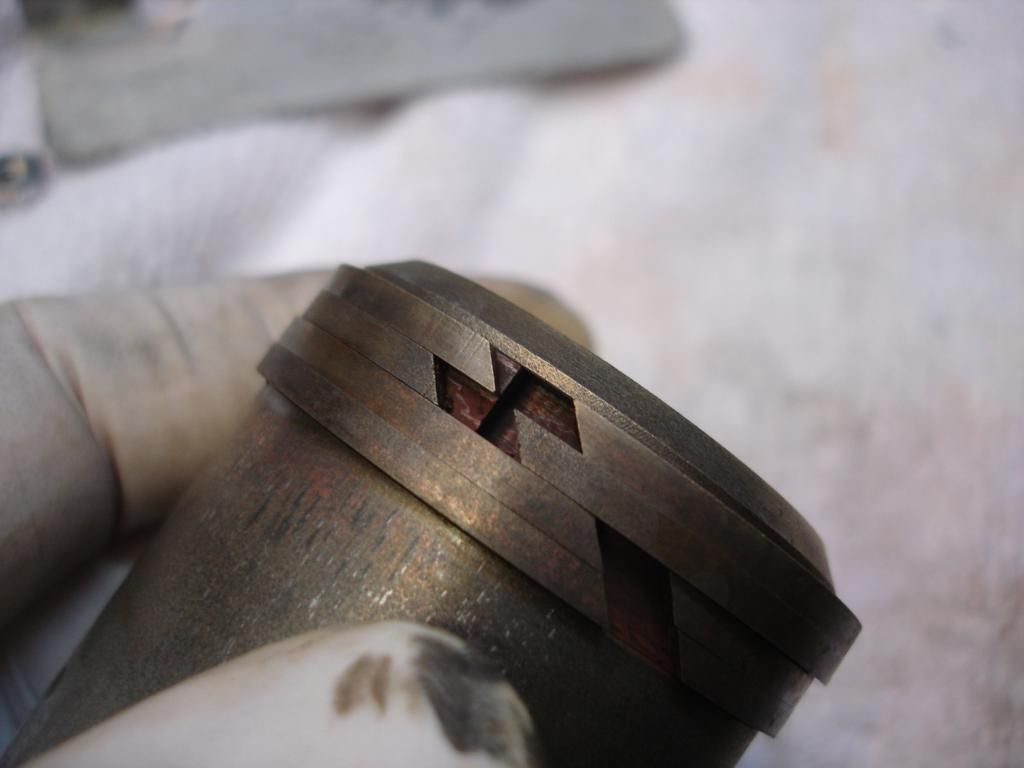
More like so...If you note the second ring is 180 degrees off from the top ring, and the 3rd ring is askew from both the top and second.
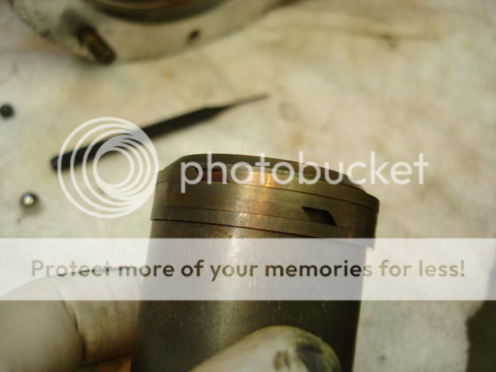
We don't have ring compressors in the modern era that will work with these rings. Lube the rings and cylinder very well and "wiggle it slowly down into position. Do not be tempted to force the piston down. wiggle back and forth, and as each ring contracts the piston will drop by the width of the ring. Eventually they will all compress and the piston slips easily to the bottom, as shown here.
The spring goes next. I have had car suspension springs less substantial than this spring. Most OD's will have an inner spring too.
Now, the solenoid plate goes on. There are 2 long screws to work the spring down evenly and slowly. Finally 2 nuts are installed on the last studs and all torqued.

More like so...If you note the second ring is 180 degrees off from the top ring, and the 3rd ring is askew from both the top and second.

We don't have ring compressors in the modern era that will work with these rings. Lube the rings and cylinder very well and "wiggle it slowly down into position. Do not be tempted to force the piston down. wiggle back and forth, and as each ring contracts the piston will drop by the width of the ring. Eventually they will all compress and the piston slips easily to the bottom, as shown here.
The spring goes next. I have had car suspension springs less substantial than this spring. Most OD's will have an inner spring too.


Now, the solenoid plate goes on. There are 2 long screws to work the spring down evenly and slowly. Finally 2 nuts are installed on the last studs and all torqued.


OP
CJD
Yoda
Offline
Now we move on to the actuator pistons. There are 2, and they each have 4 rings like the big accumulator piston. The good news, you can use a ring compressor on them, if you have one for a small bore engine. I don't, so I used the wiggle technique while carefully pressing the rings inward as they approached the bevel. Again, take you time as these metal rings are unobtainium.
Now the actuator valve. The valve goes in the hole, followed by this same ball/spring assembly used for the pump valve.
This is the assembly plug located on the top right of the case. It uses a copper washer to seal the plug.

Here is the bottom of the valve needle protruding from the bottom of the case wall.
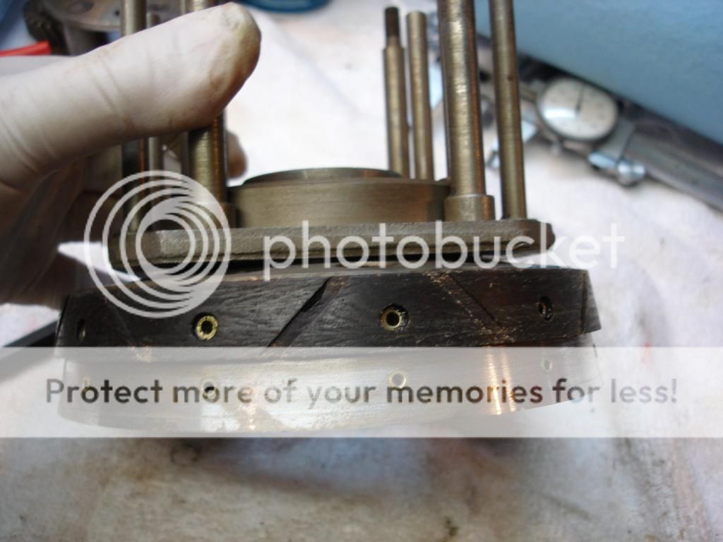
Finally, the "brake ring" goes in place. This is a big iron casting that press fits into both the case and the tail housing, like sandwich meat. The manual says "dry", but I cannot bring myself to fit any metal to metal assembly dry. I am using Loctite 518. It comes apart easily and will dissolve if any gets loose in the OD.
Notice that brake ring has a cone shape. That engages the clutch barrel to engage the OD. The clutch assembly comes next...


Now the actuator valve. The valve goes in the hole, followed by this same ball/spring assembly used for the pump valve.
This is the assembly plug located on the top right of the case. It uses a copper washer to seal the plug.

Here is the bottom of the valve needle protruding from the bottom of the case wall.

Finally, the "brake ring" goes in place. This is a big iron casting that press fits into both the case and the tail housing, like sandwich meat. The manual says "dry", but I cannot bring myself to fit any metal to metal assembly dry. I am using Loctite 518. It comes apart easily and will dissolve if any gets loose in the OD.


Notice that brake ring has a cone shape. That engages the clutch barrel to engage the OD. The clutch assembly comes next...
OP
CJD
Yoda
Offline
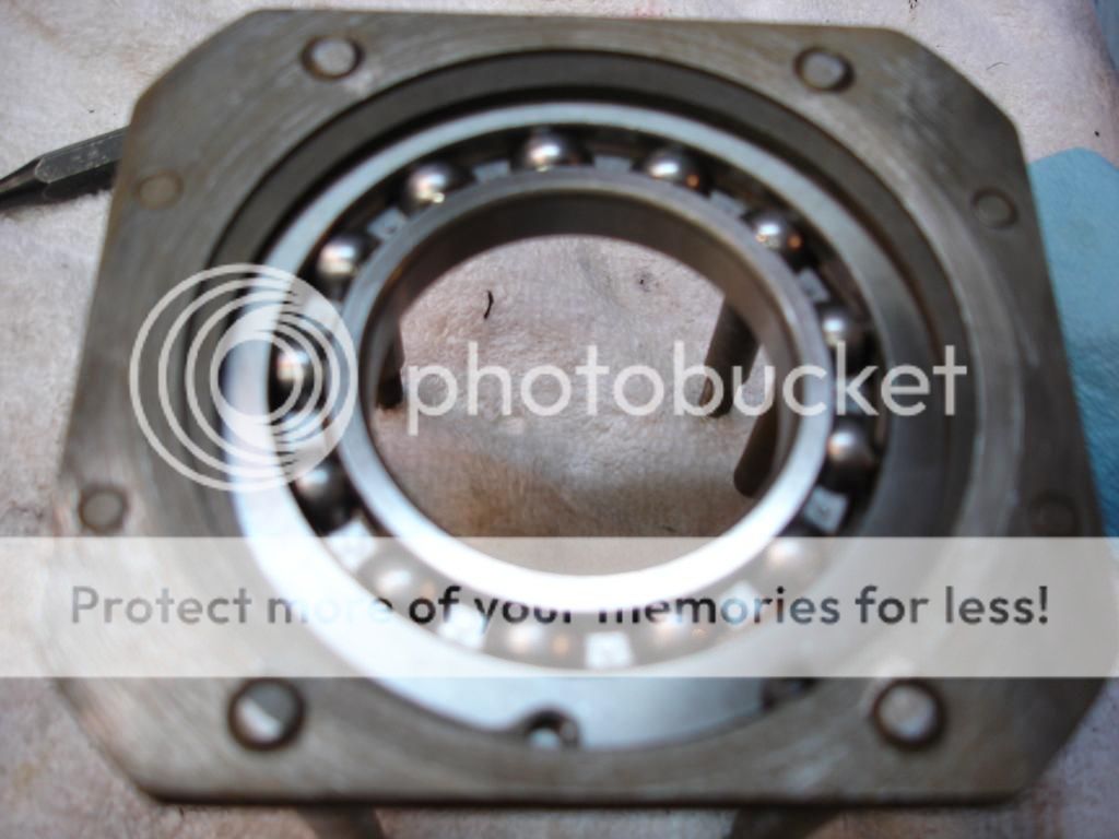
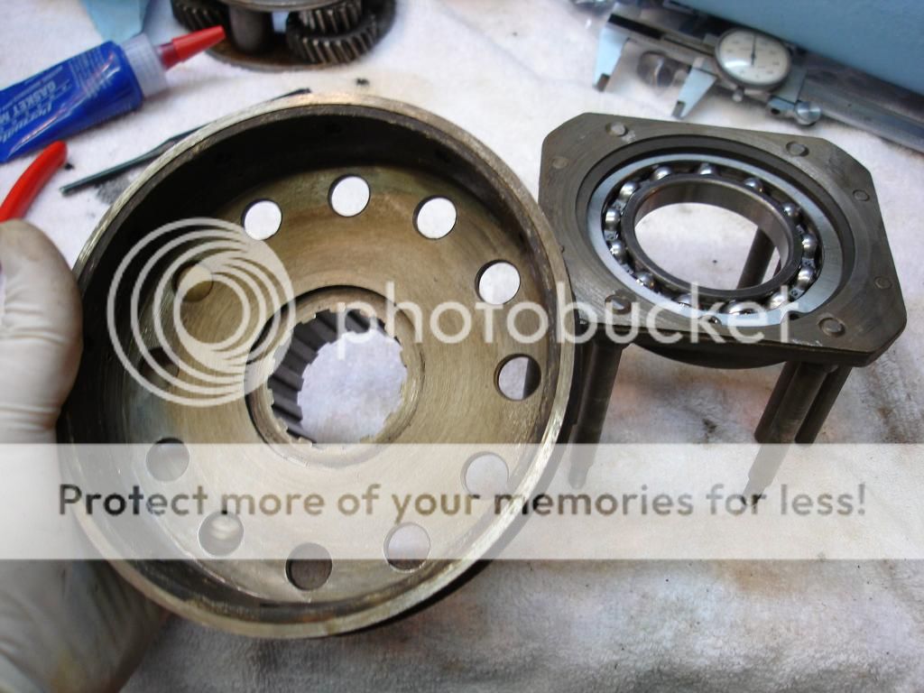
The clutch assembly goes together as follows. First, the large ball bearing is pressed into the cage. The fuzzy pic is to show the large snap ring that holds it in. This requires a heavy duty set of snap ring pliers to remove/install. I shattered 2 cheap pair removing it, so got an op to buy new tools!
This is the clutch drum. The manual doesn't call it that, but that is what it is, so I like that name. It has lining riveted to the the cone shape on both the outside AND inside surfaces. It is splined to the inner gear of the planet gearset...so it is splined to the "sun" gear...named because everything else spins around it. This is what makes the OD work.
If you picture, if the clutch drum moves to the rear, it hits the annulus cone. In this position it locks the sun gear to the annulus, or output shaft. So, the gears revolve as an inert mass of metal, and the drive ratio is 1:1. Straight through the front and out the tail shaft.
Now, if we move the clutch drum forward, it disengages the annulus, and then hits the iron brake ring that we just installed on the case. Now the sun gear is locked down tight...so the planet gearset starts to revolve around the stationary sun gear. The planet gears are splined to the input shaft, so that is what makes the gearset revolve. So now the annulus gear gets a 22% boost in speed...OD!
To make this function, we have to be able to slide the clutch drum forward and backward. That is the purpose of the sliding cage we just assembled. Now we must attach the clutch drum to the sliding cage. The drum presses into the center race of the big ball bearing in the cage.
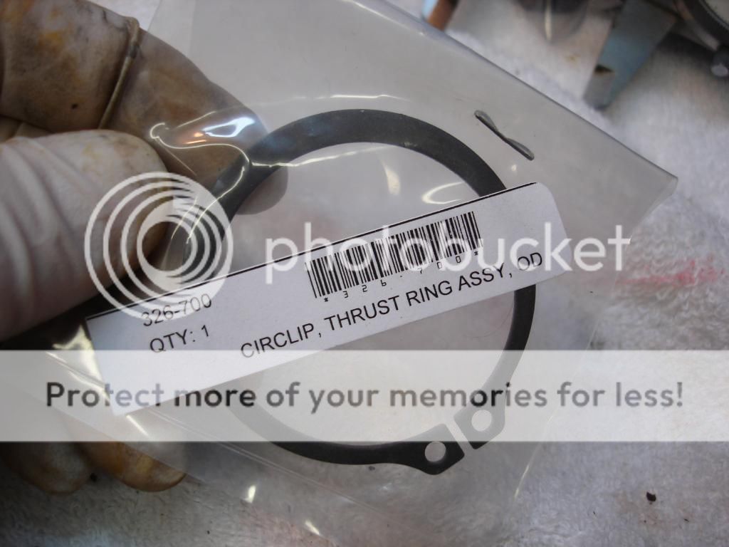
And, of course the new snap ring. This is the one snap ring in the OD I was not comfortable re-using. I know you should technically never re-use snap rings...in this case I really agree! Also another chance to use those new pliers!
Now we move back to the tail housing sitting in our vice. First, the planet gearset goes into the annulus. It starts on the bench by first aligning the punch marks on the 3 planet gears straight outward.

Now the sun gear goes into the center of the planet set.
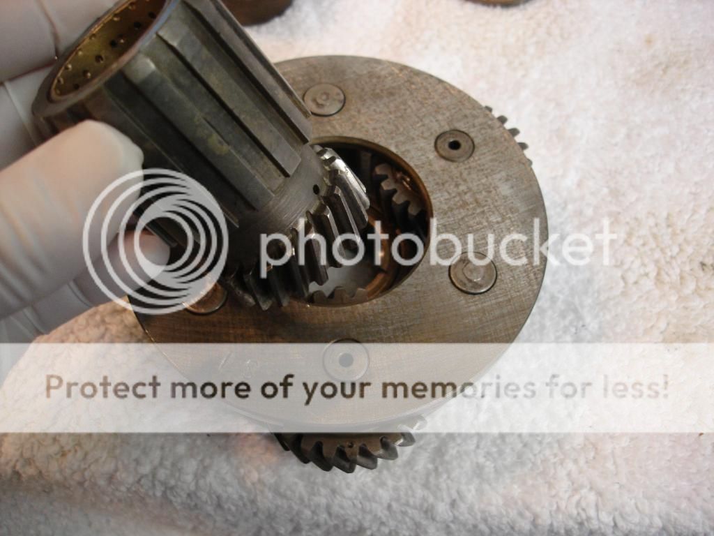
Then the whole gearset goes into the annulus.


Now we have to check the end play of the sun gear inside the assembly. Remember the clutch drum slides back and forth on the sun gear splines, so the play has to be checked. These are the thrust washer and shim used to set the gear clearance. Once again, the shim is easily available...at $20 a pop!

The washers go on the top of the sun gear...

And the main case goes on. Follow either the manual or the Buckeye article to determine the clearance. Mine was right on with the old washers.

Remove the case and the thrust washers from the sun gear.


This is the clutch drum. The manual doesn't call it that, but that is what it is, so I like that name. It has lining riveted to the the cone shape on both the outside AND inside surfaces. It is splined to the inner gear of the planet gearset...so it is splined to the "sun" gear...named because everything else spins around it. This is what makes the OD work.


If you picture, if the clutch drum moves to the rear, it hits the annulus cone. In this position it locks the sun gear to the annulus, or output shaft. So, the gears revolve as an inert mass of metal, and the drive ratio is 1:1. Straight through the front and out the tail shaft.
Now, if we move the clutch drum forward, it disengages the annulus, and then hits the iron brake ring that we just installed on the case. Now the sun gear is locked down tight...so the planet gearset starts to revolve around the stationary sun gear. The planet gears are splined to the input shaft, so that is what makes the gearset revolve. So now the annulus gear gets a 22% boost in speed...OD!

To make this function, we have to be able to slide the clutch drum forward and backward. That is the purpose of the sliding cage we just assembled. Now we must attach the clutch drum to the sliding cage. The drum presses into the center race of the big ball bearing in the cage.

And, of course the new snap ring. This is the one snap ring in the OD I was not comfortable re-using. I know you should technically never re-use snap rings...in this case I really agree! Also another chance to use those new pliers!


Now we move back to the tail housing sitting in our vice. First, the planet gearset goes into the annulus. It starts on the bench by first aligning the punch marks on the 3 planet gears straight outward.

Now the sun gear goes into the center of the planet set.

Then the whole gearset goes into the annulus.


Now we have to check the end play of the sun gear inside the assembly. Remember the clutch drum slides back and forth on the sun gear splines, so the play has to be checked. These are the thrust washer and shim used to set the gear clearance. Once again, the shim is easily available...at $20 a pop!

The washers go on the top of the sun gear...

And the main case goes on. Follow either the manual or the Buckeye article to determine the clearance. Mine was right on with the old washers.

Remove the case and the thrust washers from the sun gear.
Last edited:
OP
CJD
Yoda
Offline
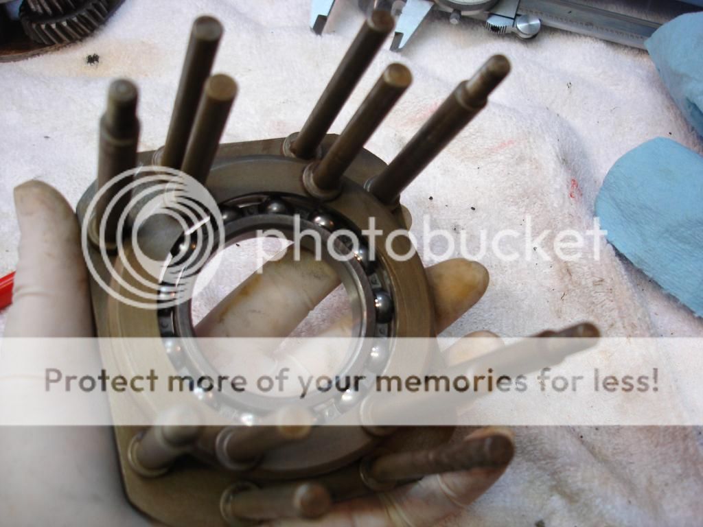
Now, with the case back off, we lower the clutch drum onto the annulus in the tail housing. It slides down over the sun gear splines with the posts sticking up.


Now put the case back on. The studs with the threads stick through the main case forward, as shown. Now, we have to have a way to grab onto these studs and pull the clutch cage forward. These bars are what do that. They are just simple bars that go from stud to stud, and over the top of the actuator pistons we put in earlier. So, picture that when the pistons move out of their bore, they hit the bars, which are connected to the clutch cage. So, the cage moves forward, taking the clutch drum with it.
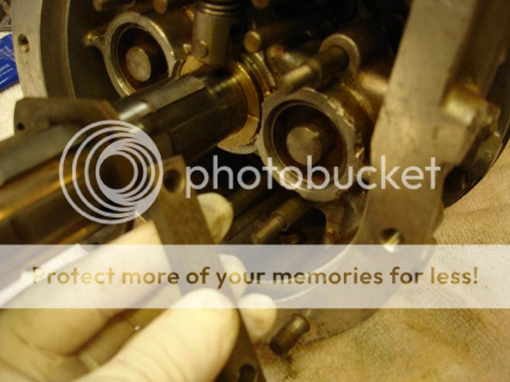


This is a terrible pic, but it shows a couple important parts. The actuator shaft goes through the OD unit at the bottom (which is towards the top of the pic). The solenoid turns the shaft on the left side of the OD, and inside the case there is a little cam block that lifts the end of the valve needle. If you can see, the cam is now in place and staked on the actuator shaft.

This is the shaft coming out the right side of the case. Another arm will be staked onto the shaft using the hole on the shaft.

Now the OD is pretty much assembled and ready to install on the tranny.
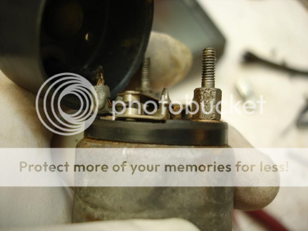
One final item worth noting. The solenoid is an interesting bit of Frankenstein technology. It has 2 coils. Both are energized to drive the plunger in and turn the OD actuating shaft, but, as the plunger hits bottom in the solenoid, it trips a contact that de-energizes the big coil, therebye reducing the amps required to hold the OD in.
I have 2 old solenoids. In both, the plunger for the contact was dirty and stuck, so only the low amp coil was active. This just shows the cap removed and the contact. I cleaned it up and all works great now. So, the solenoids are repairable, to at least some extent.

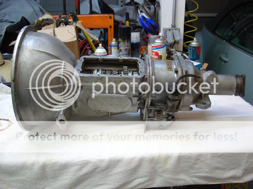
The complete overdrive is sitting vertically on the drive shaft flange in my vice. It will wait there until the tranny is complete, but that'll be another thread.


Now put the case back on. The studs with the threads stick through the main case forward, as shown. Now, we have to have a way to grab onto these studs and pull the clutch cage forward. These bars are what do that. They are just simple bars that go from stud to stud, and over the top of the actuator pistons we put in earlier. So, picture that when the pistons move out of their bore, they hit the bars, which are connected to the clutch cage. So, the cage moves forward, taking the clutch drum with it.


This is a terrible pic, but it shows a couple important parts. The actuator shaft goes through the OD unit at the bottom (which is towards the top of the pic). The solenoid turns the shaft on the left side of the OD, and inside the case there is a little cam block that lifts the end of the valve needle. If you can see, the cam is now in place and staked on the actuator shaft.

This is the shaft coming out the right side of the case. Another arm will be staked onto the shaft using the hole on the shaft.

Now the OD is pretty much assembled and ready to install on the tranny.
One final item worth noting. The solenoid is an interesting bit of Frankenstein technology. It has 2 coils. Both are energized to drive the plunger in and turn the OD actuating shaft, but, as the plunger hits bottom in the solenoid, it trips a contact that de-energizes the big coil, therebye reducing the amps required to hold the OD in.
I have 2 old solenoids. In both, the plunger for the contact was dirty and stuck, so only the low amp coil was active. This just shows the cap removed and the contact. I cleaned it up and all works great now. So, the solenoids are repairable, to at least some extent.


The complete overdrive is sitting vertically on the drive shaft flange in my vice. It will wait there until the tranny is complete, but that'll be another thread.
OP
CJD
Yoda
Offline
That's a good question! I wondered the exact same thing. I do know the Laycock manual states that the annulus, planet and sun gears are manufactured as a set, and that the gears should not be mixed between sets. What's really interesting is that they tell you to line up the planets, but there are no marks to line up either the annulus or sun gear. I looked closely and found nothing.
Maybe for balance?
Oh, and I've moved over to a new thread for the tranny rebuild if anyone wants to follow. I'll come back here when it's time to attach the OD...
Maybe for balance?
Oh, and I've moved over to a new thread for the tranny rebuild if anyone wants to follow. I'll come back here when it's time to attach the OD...
OP
CJD
Yoda
Offline
I took a pause on this thread while I waited for new OD release springs...and I rebuilt the gearbox. I'll cover the gearbox build on the other thread. But here is the finally of the OD build.
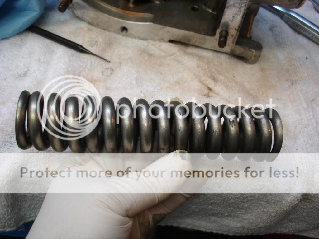
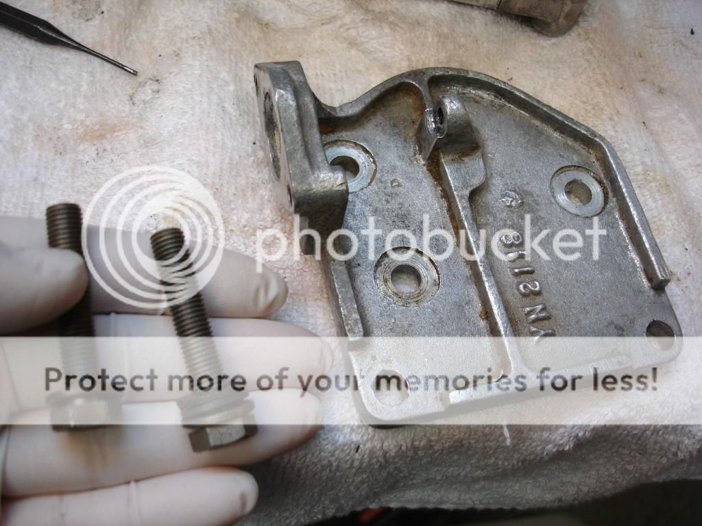
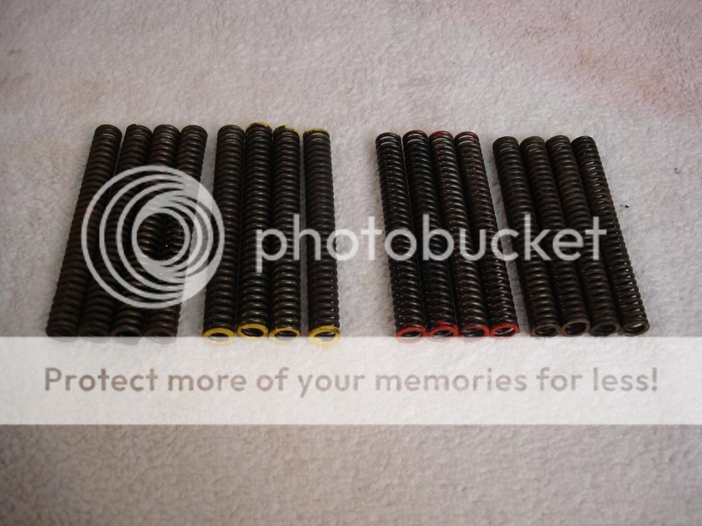
These are the OD release springs. The actuator pistons pull the clutch drum into the brake ring on the casing, and these springs push the drum back in contact with the annulus once the pistons are vented back to the case. There are 8 springs. I have them next to the originals for comparison. They call the springs "long" and "short", but as you can see, the length is almost identical. A better description is thick gage or thinner gage. I would not have replaced my springs, except the 2 at the top of the case were corroded. They only come as a set...about $64. Ouch.
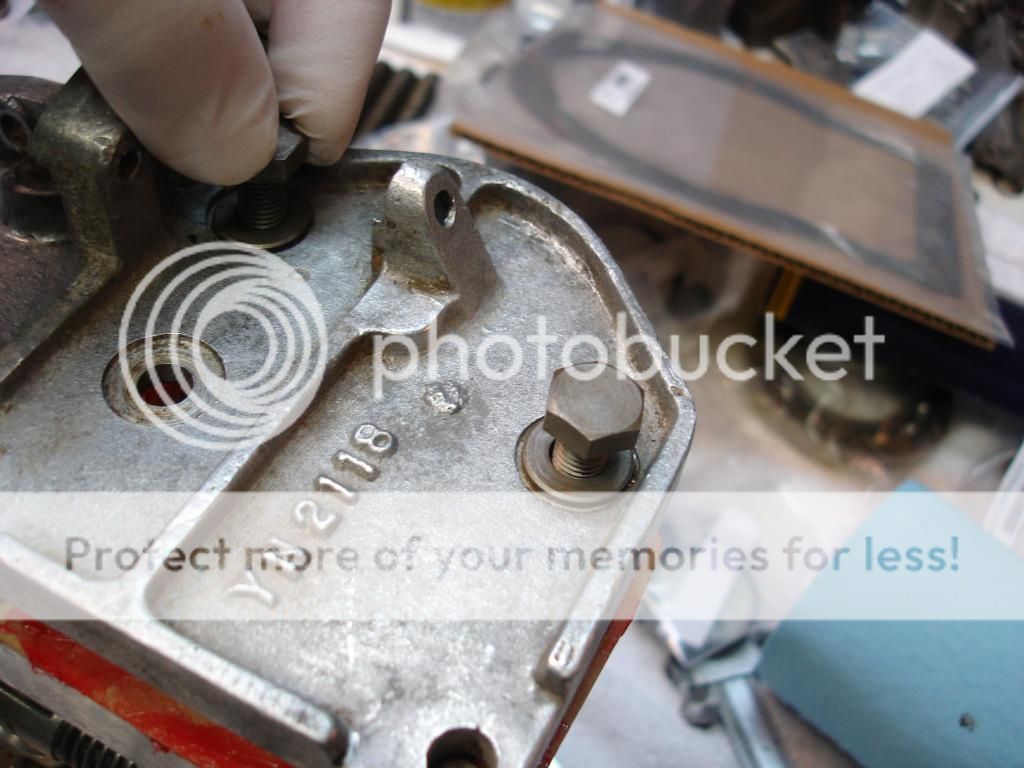
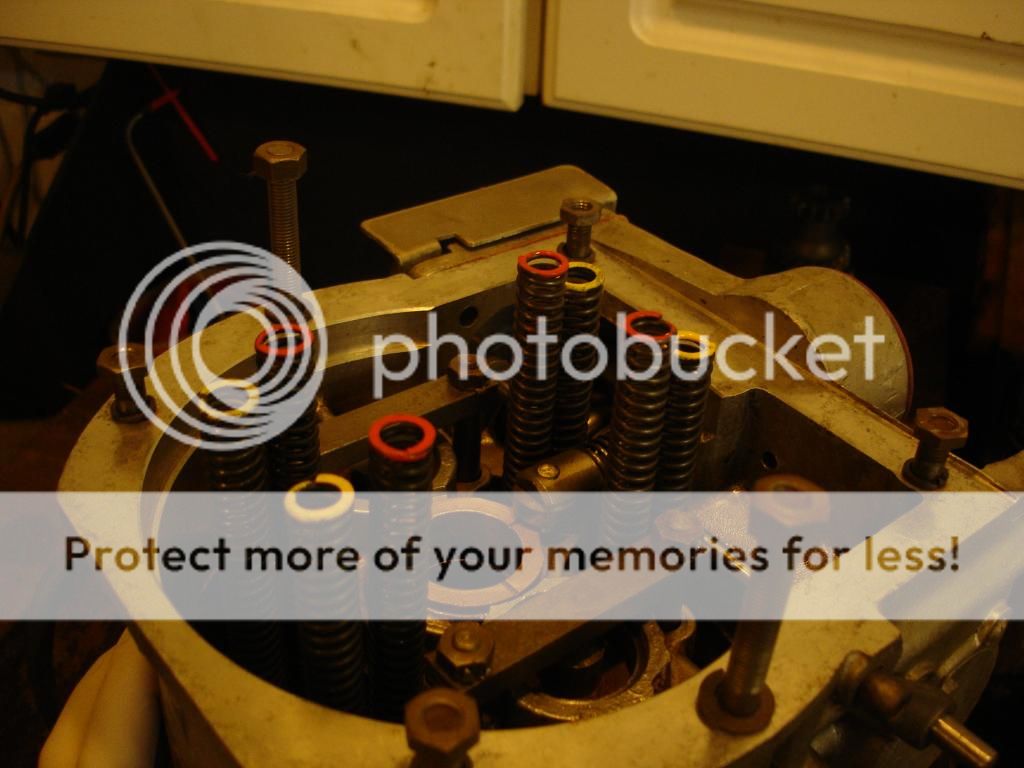
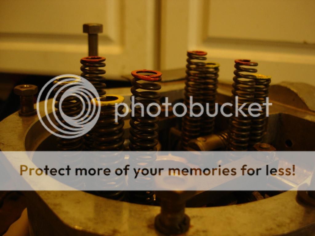
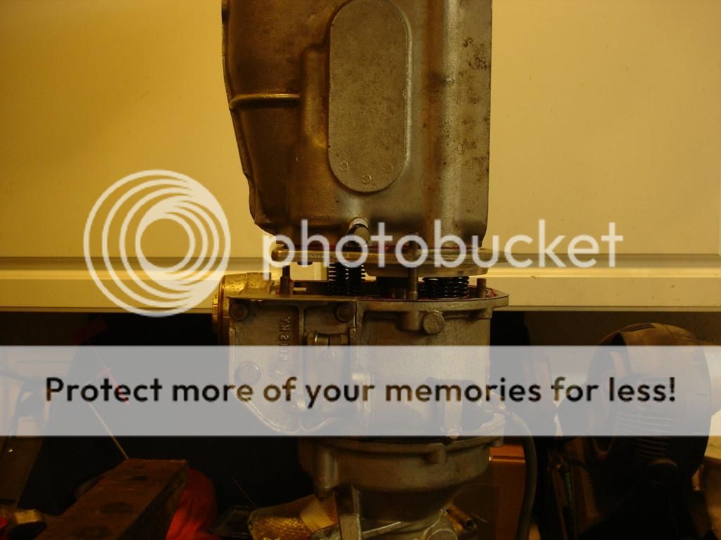
Here they are installed in the OD, which is still mounted on my vise by the drive shaft flange. Notice the inner springs stick up farther than the outer springs. This is where the gages make sense. The inner springs have to compress farther than the outer springs do. So, the inner springs must use thinner wire so they will not "coil bind". Coil bind is when a spring is compressed so far that it hits itself, metal to metal, along the entire length of the spring.
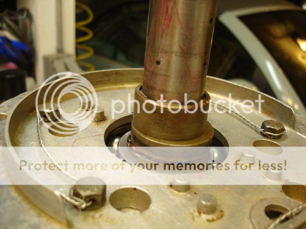
After rebuilding the tranny, the main shaft is now part of the tranny gearbox. We are going to pick up the entire tranny and lower it onto the OD. First, put the cam that actuates the OD pump onto the main shaft. This is the WRONG way!! Turn it around so the cam will be closest to the OD, not the tranny. Yes, I did have to pull the tranny back off when I realized this! Notice I used grease to hold the cam, so it won't fall while I am turning the shaft straight down to insert in the OD.
Tranny on the OD, just sitting. Notice that there are 2 long studs on the OD that pass through the tranny adapter plate. We will use these 2 studs to slowly compress the springs and draw the tranny down.


Once the tranny is set, use a screw driver to push the pump cam down against the pump roller. Then use the same driver to press the pump roller inward, and the cam falls right into place under the pump roller.
As you tighten the nuts, turn the Tranny/OD as you go so the main shaft engages everything it needs to engage. This includes the pump cam, the planet gear carrier, and the one way clutch. You don't need to know all that, but that is what happens as you turn and tighten...
And, that's an OD rebuild!
These are the OD release springs. The actuator pistons pull the clutch drum into the brake ring on the casing, and these springs push the drum back in contact with the annulus once the pistons are vented back to the case. There are 8 springs. I have them next to the originals for comparison. They call the springs "long" and "short", but as you can see, the length is almost identical. A better description is thick gage or thinner gage. I would not have replaced my springs, except the 2 at the top of the case were corroded. They only come as a set...about $64. Ouch.

Here they are installed in the OD, which is still mounted on my vise by the drive shaft flange. Notice the inner springs stick up farther than the outer springs. This is where the gages make sense. The inner springs have to compress farther than the outer springs do. So, the inner springs must use thinner wire so they will not "coil bind". Coil bind is when a spring is compressed so far that it hits itself, metal to metal, along the entire length of the spring.


After rebuilding the tranny, the main shaft is now part of the tranny gearbox. We are going to pick up the entire tranny and lower it onto the OD. First, put the cam that actuates the OD pump onto the main shaft. This is the WRONG way!! Turn it around so the cam will be closest to the OD, not the tranny. Yes, I did have to pull the tranny back off when I realized this! Notice I used grease to hold the cam, so it won't fall while I am turning the shaft straight down to insert in the OD.

Tranny on the OD, just sitting. Notice that there are 2 long studs on the OD that pass through the tranny adapter plate. We will use these 2 studs to slowly compress the springs and draw the tranny down.


Once the tranny is set, use a screw driver to push the pump cam down against the pump roller. Then use the same driver to press the pump roller inward, and the cam falls right into place under the pump roller.
As you tighten the nuts, turn the Tranny/OD as you go so the main shaft engages everything it needs to engage. This includes the pump cam, the planet gear carrier, and the one way clutch. You don't need to know all that, but that is what happens as you turn and tighten...
And, that's an OD rebuild!

OP
CJD
Yoda
Offline
Now, after all that goo and cleaning, I know the big question that everyone has is, "does it work?" Yes!
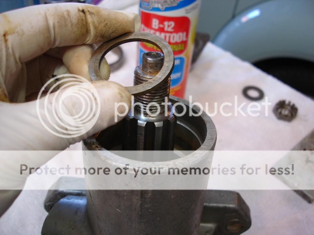
I was planning to build a cool machine to spin the gearbox and test the tranny/OD. Before I did, I looked at the input shaft and decided I didn't want to risk gouging the pilot bearing race on the input shaft, so that meant spinning the tranny from the drive shaft flange. Low and behold, when I looked at the end of the annulus shaft that mounts the drive flange, it has a little post sticking out. So, I chucked that little post right into my 1/2" hand drill and spun the OD with no fancy spinning machine!
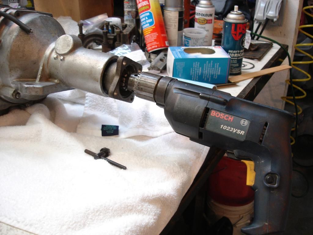
Be sure to reverse the drill, so it spins counter clockwise. Important safety tip.
Now, at first the OD was completely dead. And, after all the goo I got out of the passageways, I assumed I missed some and would likely have to heat the tranny to get it to work. Nope. It was just air in the passages. The pump only pushes a small amount of oil once per annulus revolution, so it takes considerable time to get the air out of the cylinders and passageways. Soon I could hear the solid "thwok" every time I manually moved the solenoid lever. When I release the lever, a more gently sounding "tunk" indicates it is back in direct drive. Proof that you are in OD is that, when you stop turning the shaft with the drill, it will not turn clockwise. This would be reverse in the car, and the one-way clutch will not allow the drive shaft to turn in reverse when in OD.
Soon the accumulator purged it's air, and I could spin the shaft to pump up the accumulator, and actuate the OD 3 times without even spinning the shaft While I was actuating it. "Thwok", "tunk", "thwok", "tunk"...
Last check, I used a jumper to a battery to make sure my solenoid rebuild worked. Solenoid clicks, followed by an almost immediate "thwok". Take away the 12 volts and the OD gently "tunks" back to direct drive after about a second.
I love it when a plan comes together! I have not checked pressures, but I will when I can build an adapter to hook up. It's very simple, so I cannot imagine pressures would be off.
Last edited:
Marvin Gruber
Yoda
Offline
John,
thats great! What gear did you pur tranny in and how fast does your drill turn. I Was going to build engine stand and run/ check trans that way but your way is a lot simpler.
marv
thats great! What gear did you pur tranny in and how fast does your drill turn. I Was going to build engine stand and run/ check trans that way but your way is a lot simpler.
marv
Don Elliott
Obi Wan
Offline
I tested an O/D that we re-built on my neighbour's 10" lathe. We made a plate that covered most of the input end and surprisingly, no oil splashed out. I had made a pressure gauge with a glycerine-filled gauge and we measured 325 psi pressure (type A O/D) - so we knew it would work OK.
BTW, the steel piston rings were used in the early TR2 O/D units. The later casings take a larger diameter piston and have O-rings. Theses improvements give a higher pressure, and you don't have to worry about broken steel piston rings and in my case the latest test re-build has given no problems since the re-build in 2000 at VTR in Portland Oregon.
BTW, the steel piston rings were used in the early TR2 O/D units. The later casings take a larger diameter piston and have O-rings. Theses improvements give a higher pressure, and you don't have to worry about broken steel piston rings and in my case the latest test re-build has given no problems since the re-build in 2000 at VTR in Portland Oregon.

Offline
Hello John,
Even though I have no experience with overdrives, your thread is fascinating. I keyed on Randy's comment about the planetary gear markings. This may not apply at all but I recently rebuilt the wife's (bike) Sachs 7 speed internal gear hub. The planetary gears in that have markings too and must be lined up before mating to the sun gears. There is a tool to line up and hold the gears in place while installing. As far as that gear set is concerned if they are not lined up properly the assembly will bind when attempting to operate.
I know, its a bicycle but thought it might be relevant. - Regards, Walter