• Hi Guest!
    You can help ensure that British Car Forum (BCF) continues to provide a great place to engage in the British car hobby! If you find BCF a beneficial community, please consider supporting our efforts with a subscription.

    There are some perks with a member upgrade!
    **Upgrade Now**
    (PS: Subscribers don't see this gawd-aweful banner
Tips
Tips

Graduation! My cam has been degreed!

2wrench

Luke Skywalker
Country flag
Offline
Excited now, Forum Members. I have properly degreed my
cam and placed the timing chain on along with the timing
gears. Yahooooo! Calls for four bananas for this one!

:banana: :banana: :banana: :banana:

Also, while I recognize all supportng members, I want
to mention a Mr. D. K. Lawson, who sent me a computer
printable version of a degree wheel. I used his because
it was a full 8-inch version (sometimtes size matters)
and I could read the thing better than any others. Thanks,
DK.

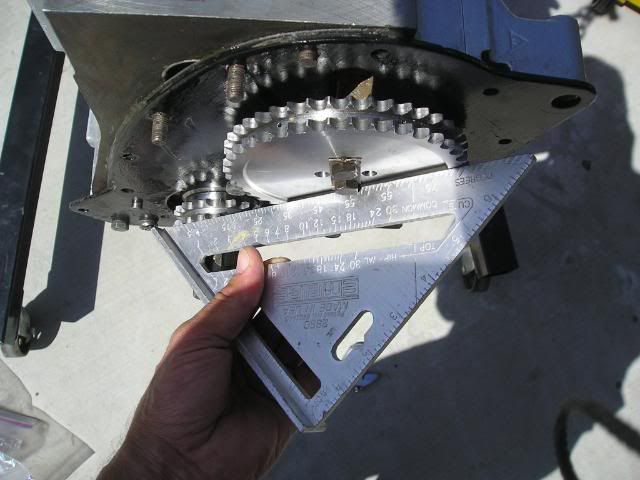
First, I installed the crank gear and bolted on the cam
gear torqued to spec temporarily to align and verify that
the gears line up well....and they do:

P1010001-32.jpg


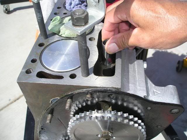
Next I dropped a lifter (cam follower) into the number one
intake valve (second back from the front of the engine)
and dropped in a properly oriented push rod:

P1010003-29.jpg


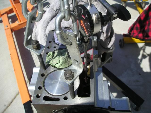
Next I placed my magnetic-based dial gauge indicator on top
of the push rod and rotated the cam gear until that push
rod was pushed to its highest point. As I rotated, it would
hit the high spot, then begin to descend; so rotate back
up again until I felt in my wrist/the cam gear, and also
watching by eye, that the push rod was up at its peak.
This is where we want to be. Leave it right there.
So far, so good:

P1010004-26.jpg


The next step was to make a pointer that would be attached
to the engine that would remain solid and static for reading
the degree cam protractor (the one received from Lawson).
I went the the wife's kitchen (opps, did I say that?)....
I mean, my old tool box and pulled out a shish-ka-bob
skewer. The one I used encircled itself at one of its
ends, so I used this end to put a bolt through with a
washer and snugged it into place with one of the bolts
from the timing chain cover, then bent the metal into its
closest position pointing to top dead center:

P1010008-22.jpg


A visit to Orchard Supply Hardware produced a smaller-in-length
but properly threaded bolt that will temporarily be placed
into the end of the crank holding the paper-made protractor
which I printed from my computer and pasted onto cardboard.

Here I show myself snuggin the bolt down with the protractor
set a 0 degrees top dead center; numbers one and six pistons
at top dead center:

P1010009-21.jpg


Now a close-up with everything snugged and fine tuned and
ready to twist the crank to its proper orientation:

P1010010-21.jpg


Now a pause: As every cam that is other than OEM spec,
a performance cam (albeit gentle) such as mine is going
to be set to different specifications. My cam is a
new (not reground) BP270 purchased from British Parts Northwest. (Good guys). They did forget to send the
installation instructions, but I got them immediately
via internet once I contacted them. No big sweat.

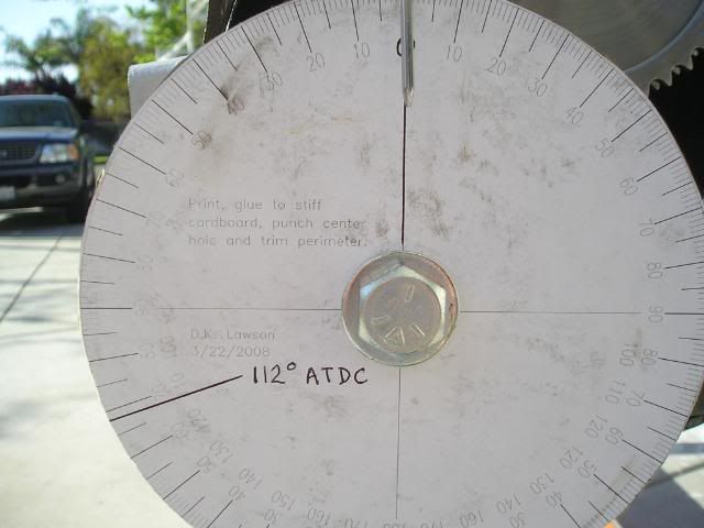
So my specs called for turning the crank (now that we are
at the point shown in the pictures) to the position of
112 degress ATDC, which stands for: After top dead center.

That means the crank was rotated clockwise, now, slowly
watching the pointer untill the protractor showed 112
degrees to the left side of zero, which is after top dead center. I darkened this degree line in for easy reference.

I noticed, when doing this, that two other pistons shifted
into position of top dead center. Instead of one and six
there, two and five moved up to top dead center.

This is proper orientation for cam to crank. Each,
respectively, are left where they are and the timing
gear is installed.

What actually happens is that as the chain is put into
place, (remove the cam gear; start by placing onto the
crank first, then placing onto the cam gear...), a slight
movement of the cam one gear tooth left or right must take
place (unless of course you have an adjustable cam gear).
I was told this amount of loss in perfection is negligable
and adjustable gears are mostly used for racing engines.

So, on went the timing chain and I'm a happy camper.
Now, I need to rest, but you know I'm such a blabber
that I'll be back on soon with more to say, more than
likely.

Now I'll sit to think about what is coming...and I do
have questions to ask. I need to organize my thoughts.

Cheers,
 
I get it know. I had the shop do this for me when i had Ted's cam put in my 6.
Very good lesson. Your in Paul and Dales league now. Someone should stickey that thing.
 
Excuse the intrusion ---
Quote:
-------------------------
"a slight movement of the cam one gear tooth left or right must take place (unless of course you have an adjustable cam gear). I was told this amount of loss in perfection is negligable and adjustable gears are mostly used for racing engines."

"That means the crank was rotated clockwise, now, slowly
watching the pointer untill the protractor showed 112
degrees to the left side of zero, which is after top dead center. I darkened this degree line in for easy reference.

I noticed, when doing this, that two other pistons shifted
into position of top dead center. Instead of one and six
there, two and five moved up to top dead center."
---------------------------

Never heard of such a strange way of setting cam timing. 1/2 tooth off could be as much as 8 degrees. Enough to totally screw things up.

Also, the max intake opening point at 112 degrees is hard to determine. There can be several degrees of rotation at the nose of the cam where there is very little lift change. Since there is 120 degrees between crank throws, the other two should NOT be at TDC.

What ever happened to the old way of exactly finding TDC via positive stop & then finding exact intake & exhaust valve opening & closing points at .050" lift, or what ever lift the cam maker specifies? You not only want to be sure that the cam is installed correctly, but also that the cam has been ground to correct specs.

You could hit it lucky. Or have to take things apart later to get it correct, or never know that it could run much better. Why take a chance when it's so easy to do it right the first time.
Good luck,
D
 
Without an adjustable cam gear you don't need to dial the cam in the nearest to the exact position will be the manufacturers timing marks.To adjust it exactly an adjustable cam sprocket is essential and I disagree that having to move the cam sprocket is negligible,the whole point of dialling the cam in is to get it exact and if it is not you will not get the benifit of the change of cam,it could even run worse.Also I agree with Dave Russell that the nose of the cam lobe holds the valve fully open for a few degrees and it should be timed at the specified opening.Have you sorted the binding on the cam retainer first?
 
Thanks, Dave and thanks, Mike.

First, Dave, absolutely no intrusion here. I am on the
Forum for the feedback and points of view/experience
of all parties here. I appreciate you looking in and
taking your time to comment. A good friend will say
what needs to be said.

I gather from my reads that this method of degreeing
the cam would be utilized in lieu of having the head
in place. Since the head is not in place, I used this
approach, and if I'm not mistaken, it had been described
to me here on the net as an acceptable approach. That
said and in considering your comments, I will be reviewing
my work and reconsidering my opitions.

I think what you describe would involve....well, I'm
not so sure, so maybe you could describe the positive
stop method.

Mike: I am satisfied with my cam retainer installation.
Snugged her up and acheived .004 end float, after some
doing.
 
I have bought the same cam and will be installing the same way. I called Greg at BPNW and asked if the new cam could be put in the same way you would install the old (standard) cam. He said NO, install it the way the instructions say. I too have the degree wheel from 2wrench and will be doing this soon. I really don't understand why you can't since the new cam is merely ground onto the old core, but Greg has likely built more engines than me.

You can fip the cam gear around several ways and maybe not have to move the came to get the bolt holes to line up.
 
billspit said:
He said NO, install it the way the instructions say. ...... I really don't understand why you can't since the new cam is merely ground onto the old core, but Greg has likely built more engines than me.

You can fip the cam gear around several ways and maybe not have to move the came to get the bolt holes to line up.

The new cam may not be symmetric like the old one, so the procedure in the book would not put it in the correct location.

By flipping the cam gear and changing the relation location you should be able to get within 1/4 tooth.


See this explanation from the Kent Cams web site:

Cam Timing:

There are a number of different methods of cam timing. We at Kent Cams use either the 'Lift at Top Dead Centre' method, or the 'Full Lift Position method'

Full Lift Position method:

For many years the most commonly used method has involved establishing top dead center (TDC) as a datum (zero degrees) and positioning your camshaft with its inlet valve at maximum lift at a given position relative to this datum.
For example take our Ford x/flow camshaft number 234 which has a quoted figure of inlet timing @ full lift = 103 degrees. This means that the inlet valve should be set to be fully open at 103 degrees after top dead center. Therefore using a protractor or timing disc you can establish 103 degrees after TDC and it is at this point that your inlet valve should be fully open. Minor adjustments from the standard timing point can be made with the aid of adjustable timing kits or an offset dowel.

Lift at Top Dead Centre:

In recent years with the proliferation of multi valve/multi cam engines this method can be a labourious hit and miss affair. This is solved by setting all of your camshaft timing at a specified lift at the previously used datum of TDC.
This Method has been in use by Kent Cams and many top engine builders for many years. This method is relative simple and has the benefit of setting individual cams at the same position without resorting to excessive crankshaft rotation.
For example the Ford x/flow camshaft 234 has a quoted 'TDC' lift of 2.84mm. This means that when the piston is at overlap top dead centre (not the firing TDC) the cam should be set so that the inlet valve has 2.84mm of lift.
 
"...the other two should NOT be at TDC."

I've looked at this, Dave, because it would have to be really, really wrong
if this premise is incorrect. Maybe you misunderstood my comment?

As the crank was rotated clockwise so the pointer is at 112 degrees AFDC,
at that very point I noticed that pistons 2 and 5 were moved to the top.
As I continue to rotate the crank one full turn and back to the top, my
pistons 1 and 6 are right back to top dead center.

So, it is just to note that with the cam degreed as per instructions, that
pistons 2 and 5 moved to top dead center coincidently or concurrently with
the required 112 degree ATDC, at which time the intake valve is in its
full open position.

Hope this clarifies and gives this install the thumbs up. If not, I do
appreciate hearing what is wrong and why. I will correct it, if necessary.

Also, a thought is that once the head is on, I think there would then be a
way to verify the installation by checking the gaps on the last two valves,
or some such thing. I'll go there, if all else seems well.

Thanks,
 
2wrench said:
As the crank was rotated clockwise so the pointer is at 112 degrees AFDC,
at that very point I noticed that pistons 2 and 5 were moved to the top.
-----
pistons 2 and 5 moved to top dead center coincidently or concurrently with
the required 112 degree ATDC, at which time the intake valve is in its
full open position.
I knew I should have stayed out of this.
There are exactly 120 degrees between crankshaft throws. If #1 is at 112 after TDC, the next pair should be at 8 degrees before TDC. For illustration only, if #1 were at 120 degrees ATDC, then the next pair would be at exact TDC.

Look here to get good info & about the positive stop to find TDC. In your case, a positive stop could be a bar across the cylinder bore with a stop bolt threaded into it.
www.cranecams.com/?show=article&id=3

There are several ways to meet the objective. I'm just questioning the accuracy of your method & the numbers.
D
 
Cut a new and different degree wheel and followed the directions that came with the cam as is described above.

Tried turning over the cam sprocket and found that the
holes lined up perfectly. Bolted snug; verified
again gear sprockets line up with a straight edge again,
and they do.

Guess I won't be needing the adjustable cam sprocket I
ordered. Maybe I'll trade it for a nice-looking
valve cover or something.

I reconsidered everything and I'll go with following
the directions that came with the cam. Always hoping
I don't make any dumb mistakes.
 
Hmmm. Dave, I have slept on this and I think I
appreciate your concern. Very simple concept.
You say that pistons 2 and 5 should be about 8
degrees shy of being top dead center, if the crank
was oriented to 112 ATDC, because there are 120
degrees between crankshaft throws. Got that.
Hmmmm. Wonder if my protractor is slipping or off
or something. Is this 120 degrees between crank
throws an industry standard? Could my cam be any
different because it is a performance type?
 
For a 6 cylinder engine it has got to be 120 degrees, 120 plus 120, plus 120 equals 360 degrees, unless the crank has been twisted.

It is normal for a few crank degrees to occur(on the degree wheel) while the piston is at tdc and bdc, while the crank journal is swinging through it's arc. That's why the recommendation of a piston stop, and the necessity to measure going in both directions of rotation and halving the difference.

So you might be closer than you think and 112 could very well be 120, especially if you are repeating that reading.
 
:iagree:

For what you're doing, Den, the "piston stop" method of determining TDC may work best for you. The degree wheel may in fact be slipping as well.

The 120* as Ron explains is dictated by the number of cylinders and running balance for "smoothness". A four banger has the throws of the crank 180* from one-another. Most English fours have 1&4, 2&3 as "twins". Firing order will give you an insight to which ones are "paired" on the crank.

Four stroke engines see the crank making two revs for every one of the cam, so the #6 cylinder on yours has fire as the #1 is on intake stroke. Each firing cylinder sees its corresponding "twin" sucking fuel. This is on in-line engines... V configurations and "boxer" types are a different animal (sorta) due again to running harmonic balance issues.
 
When I used to build old engines, I found TDC with a degree wheel and dial gauge.
Mount the degree wheel on the crankshaft end, with a thin pointer on the block (a la 2wrench setup). Mount dial gauge with plunger on the no.1 piston.
Rotate crank until dial gauge indicates piston at top. Note the pointer position on the degree wheel.
Then rotate back and forth slightly - note on the dial gauge when the piston has dropped (say) 10 thou either side and mark your degree wheel.
You should now have 3 marks on your degree wheel; 10 thou on the piston's way up, TDC, and 10 thou on the way down.
If TDC isn't exactly between the 10 thou marks, it isn't TDC, so do the exercise again and again until it is.
Which is, I guess, what Ron was driving at.
When you've found TDC, mark it in a way you won't lose it ever again. Maybe scribe marks on timing gear or sprocket and block, or flywheel if fitted (my favourite because it's so big, it's more accurate).

I don't like the "valve lift" methods of dealing with cam timing with an OHV engine. Rocker clearances and ratios can screw that up at worst, and have the risk of confusion. Cam lift is fine, though.
 
I use a dial as well, Roger, but figger since Dennis is a relative newbie at this it would be a bit less taxing to locate TDC with the "stop" method. Just one opinion, so treat as such. :wink:
 
I meant for this to be a learning experience.

Top dead center (piston one) is already marked onto my rear engine plate. Looks right and feels right; i.e., three
mark lines in a row, center mark puts piston one at
top dead center (both by look and by feel).

Where the numbers don't add is:

Intake valve set full open.

Crank turned from TDC to 112 ATDC.

This is the problem: At this point pistons 2 and 5
are at the top of the block (TDC). Dave has said this
shouldn't be because that would have to put the
(what is supposed to be 112 at 120 instead).

That said, in doing these exercises, I did have a time
where when I turned to 112 ATDC, pistons 2 and 5
were not all the way up, and when I continued to
move to 120, they were.

So, I will do and redo this. Maybe my protractor is
slipping or something.
 
Checked again early this morning. What I'm finding is
that when I described pistons 2 and 5 at TDC; actually,
it may not have actually been TDC. I mean, it was
close.

For instance, I could move all the way to 120 AFTDC
and there would be little change in the movement of the
pistons. They could be very close to the top of the
block and actually move very little between, say 112 and
120, but be very close to the top of the block nonetheless.

Don't know the stop method. Sounds more difficult,
taking readings on the dial indicator at specific
points, etc.

I think I could have it right. Thought I read somewhere
that with the head on, if the last two valves open the
same "on the rock," whatever that means, that the cam
is degreed well. Looking for that as verification.

Any other suggestions?
 
The "stop method" was described in either this or another of your threads.

It's ~easier~ for a novice than a dial indicator.

A piece of strap steel, at least 1/8" thick, 1" wide, mmm... eight-ish inches long... Two holes (one at each end) to allow you to mount it so it goes across the bore of #1 in approximately the middle. A hole drilled thru it in the approximate center of the cylinder to accomodate a cap screw and nut.

The idea here is that you are introducing a definite "stop" for the piston at a place BEFORE TDC and ATDC you can measure with the degree wheel. Where it stops on the degree wheel in both directions can then be "halved" accurately to determine actual TDC. A dial indicator needs "fiddling" with to get accuracy. The piston is static for a degree or two as the crank throw transitions from "up" to "down".


Izzat makin' any sense?!? :jester:
 
Maybe I'm missing something, but how do yo know the kebabpointer is pointing where it needs to be relative to the crank/degree wheel? Seems like a bend would introduce error.
 
Back
Top