• Hi Guest!
    You can help ensure that British Car Forum (BCF) continues to provide a great place to engage in the British car hobby! If you find BCF a beneficial community, please consider supporting our efforts with a subscription.

    There are some perks with a member upgrade!
    **Upgrade Now**
    (PS: Subscribers don't see this gawd-aweful banner
Tips
Tips

Fuel sender internal wire

RestoreThemAll

Jedi Warrior
Country flag
Offline
In the attached pic you can see a bare copper wire. It may be part of the internal winding? I'm not sure why it sticks out that far. I've looked at other pictures and none of them show that wire. Not shown in the pic...it seems to be insulated from the post and runs by the body. Is it a problem? Should it connect to ground?
 

Attachments

  • Dales original fuel gauge sender.jpg
    Dales original fuel gauge sender.jpg
    32.7 KB · Views: 141
In the attached pic you can see a bare copper wire. It may be part of the internal winding? I'm not sure why it sticks out that far. I've looked at other pictures and none of them show that wire. Not shown in the pic...it seems to be insulated from the post and runs by the body. Is it a problem? Should it connect to ground?

Can you show a better picture of where the wire originates?
 
Yes, steve. Later tonight. I'll pop the top off and remove the post nuts.
 
From the picture in your first post it looks like a previous owner has run the additional wire under the insulating washer for the sending unit lead to provide the sender housing with an earth connection. I personally would not have connected it there on the chance it would create a leak path. Were I running a separate earth wire I would make sure the housing had a clean bare spot around one of the screw holes and fit a ring terminal and wire to the screw that goes in that hole.
 
Hi Dale,

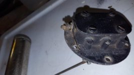
Keep in mind that the sending unit needs to be grounded. Since the tank is isolated from the grounded frame with non-conductive material under its mounting straps, the ground is provided to the tank/sending unit by the metal fuel line connected to the fuel pump. If an inline filter is installed in front of the pump (between the tank and pump), the solid metal fuel line is often severed and the rubber tubing mounting the filter. In this situation, the ground is lost and many have installed a ground wire between the sending unit and boot ground location to recover this needed grounding.

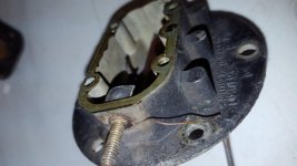
If this is your situation, I don't think a bare grounding wire would have been used so close to the connector and it is more likely that the bare wire lost its insulation when being severed during removal. However, if this is a grounding wire, as Doug L mentioned, why would wouldn't they have placed the ground wire under a convenient cleaned cover screw?

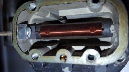
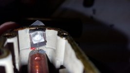
All in all, the only way to verify this to be a separate grounding wire is to remove the cover and see how it is attached. As you have mentioned, it could be part of the coil winding wire, but if so and the top was not removed prior, how did it get to the outside?

Ray(64BJ8P1)
 
Last edited:
From the picture in your first post it looks like a previous owner has run the additional wire under the insulating washer for the sending unit lead to provide the sender housing with an earth connection. I personally would not have connected it there on the chance it would create a leak path. Were I running a separate earth wire I would make sure the housing had a clean bare spot around one of the screw holes and fit a ring terminal and wire to the screw that goes in that hole.


That is an ideal solution for this application DK.
 
This wire looks like its original, no? Maybe one of you electrical experts can explain this one?
 

Attachments

  • Dales fuel gauge sender 4.jpg
    Dales fuel gauge sender 4.jpg
    38.1 KB · Views: 143
  • Dales fuel gauge sender 5.jpg
    Dales fuel gauge sender 5.jpg
    47.1 KB · Views: 128
Last edited:
Is it coming out of a minute hole to the right of the post?

Am sure it's a PO-added ground wire. The internal wire from the winding goes to the post which is insulated from the chassis.

I like to run a ground wire from one of the top-plate screws to a good ground in the trunk.
 
I took a better picture of the inside. The red arrow shows the wire that protrudes outside of the body. The grey arrow points to the 2nd wire in the foreground, slightly blurry.

If I hook this up directly to a 12v battery and the fuel gauge with the ground from the battery touching only that exterior wire then wouldn't that prove it's a ground, or not? Is there a risk of damaging the gauge?
 

Attachments

  • Dales fuel gauge sender internal wires.jpg
    Dales fuel gauge sender internal wires.jpg
    23.8 KB · Views: 117
If I hook this up directly to a 12v battery and the fuel gauge with the ground from the battery touching only that exterior wire then wouldn't that prove it's a ground, or not? Is there a risk of damaging the gauge?

If you have a multimeter, set it to measure Ohms or continuity. make sure the end of that extra wire is clean and free of corrosion. Then clean a spot on the sender housing to expose clean bare metal. Use your meter to measure between the wire and the bare spot on the sender. If you find very low resistance (in the order of 1 Ohm or less) the extra wire is connected to the sender's earth.

Regardless, even if this proves to be an earth wire for the sender, a much more common and easy to implement earth connection is to clean under and around one of the sender cover screws as mentioned above. Take a black 16 AWG wire and terminate it with a ring terminal. Place the ring terminal end of the wire under one of the cleaned sending unit cover screws and connect its other end to the car body.
 
If you have a multimeter, set it to measure Ohms or continuity...Use your meter to measure between the wire and the bare spot on the sender. If you find very low resistance (in the order of 1 Ohm or less) the extra wire is connected to the sender's earth.
I would measure resistance between the sender's output post and that bare wire to make sure there is no contact.
 
Regardless, even if this proves to be an earth wire for the sender, the minuet the wire is wrapped around the cover screw and the screw is tightened the wire will break!

Built in failure mode.

Sugested measurements very good Idea.
 
I would measure resistance between the sender's output post and that bare wire to make sure there is no contact.

If the wire is an earth connection, there will be some level of continuity between the output post and the extra wire.
 
Back
Top