• Hi Guest!
    If you appreciate British Car Forum and our 25 years of supporting British car enthusiasts with technical and anicdotal information, collected from our thousands of great members, please support us with a low-cost subscription. You can become a supporting member for less than the dues of most car clubs.

    There are some perks with a member upgrade!
    **Upgrade Now**
    (PS: Subscribers don't see this gawd-aweful banner
Tips
Tips

Fuel Pump Issues

Mowgli81

Member
Offline
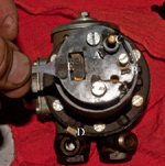
At one time the fuel pump worked fine then the car sat for 2 years w/o being started. With the ignition on the fuel pump has power but the pump itself is silent. I did find some almost cloth like particulate matter in the pump when I disassembled but it should have easily flowed throught all lines.

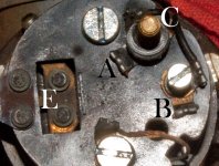
Here are my questions: see labeled picture for reference.

E: How do the points look? I firgure I should clean them but would this cause a problem.

(positive ground) D: this is where the chassis was connected and a red line was connected to post C:. I'm assuming no one switched the electrical but want to make sure that it was connected properly?

A-B: there looks as if there was a wire that was removed between these two points. Upon Close inspection it appears to have been snipped. Was this removed for the Positive ground?
 

Attachments

  • 27966.jpg
    27966.jpg
    90.7 KB · Views: 437
After Seeing the picture its a little tough to discern so I thought I'd post a better pic. Thanks for the help.
 

Attachments

  • 27967.jpg
    27967.jpg
    99.5 KB · Views: 434
Hoo boy, where to start ...

You need a new points set. Don't mess with those; they're shot.

re: "(positive ground) D: this is where the chassis was connected and a red line was connected to post C:. I'm assuming no one switched the electrical but want to make sure that it was connected properly?"

Post C is your hot lead; there is an external ground lead--though it's not strictly required--but it connects close to the pump head. The (unlabeled) post on the bottom of your photo is the ground lead--note the bare wire coming from the points set--it grounds to the pump body which grounds either/both through the chassis and the external ground lead.

Looks like this pump has been miswired in the past--the two cut wires look wrong. The two leads coming from the pump body are correct--one goes to the hot lead (A) and one to the ground circuit (B). The points are a throwover mechanism that completes the circuit to ground. There are specific settings for clearances and points offset so they get a wiping action as they open and close. Also, the diaphragm--which also operates the points mechanism by way of a shaft--has to be adjusted properly after points have been installed or messed-with. We can help, but you need to get some parts first.

Your pump should have a diode that prevents excessive arcing across the points when they open (older models used capacitors, but the diode is marginally more effective). Moss Motors has the original-style 'canister' diode, or if you're electrically savvy you can wire your own. The leads of the diode connect the hot and ground leads, but of course must be properly biased else they'll be a dead short (the 'factory' diode has red and black leads).
 
Mowgli81 said:
... .

E: How do the points look? I firgure I should clean them but would this cause a problem.

(positive ground) D: this is where the chassis was connected and a red line was connected to post C:. I'm assuming no one switched the electrical but want to make sure that it was connected properly?

A-B: there looks as if there was a wire that was removed between these two points. Upon Close inspection it appears to have been snipped. Was this removed for the Positive ground?

The points do look like they could use cleaning. A small flat points file, rather than sandpaper should be used.

A-B: fule pumps have used condensers or diodes to make the points last longer. When a diode is used, the pump is polarity specific, ie, it's for negative or positive ground, not both. One way that was used to make them not polarity specific, ie for negative and positive ground, was to snip out the diode. That looks to be the case here. Of course, the points don't last as long.
 
Perfect just what I needed. Cleaned the points up checked the ball valves for clean operation put it back together and Francis (she) fired right up and purred like a big kitty! (my buddy's name not mine :smile: ) Thanks again for your help!!
 
Based on some other comments Look like I'kll have to keep an eye on this and maybe rebuild or replace. Thank you Big G, Bob, & John. I'm sure I'll be back if she need some more work in this area.
GG
 
Hi Greg,

First, your SU fuel pump uses tungsten points that will form an oxidation layer if inactive. I would suggest you dress the points with a points file to clean off the oxidation and you should be OK after installation. If the points are excessively burned, you may need to replace them. You may also need to clean the body and adjust the diaphragm. If so, I believe Dave DuBois has the procedure on the site suggested above by Hans.

Going further, you may wish to do a simple install of a bi-polar Transient Voltage Suppressor diode between ground and the points base to ground off excessive voltage buildup that causes flash and point burn. Use a TSV with between 22v and 28v specification. The price of this electronic component is around $1.10 from a major on-line electronic suppliers (Digi-Key or Allied Electronics) with the actual unit costing around $.25. This will significantly extend point life, however, you will still need to dress the points occasionally to eliminate oxidation buildup.

By the way, this is a bi-polar unit and will NOT establish a polarity to your pump.

Hope this helps,
Ray (64BJ8P1)
 
Now that I think about it, the cut wires on the A and B terminals were probably the leads to a diode. Someone might have removed the diode--though cutting the leads is pretty tacky--if they changed the car's polarity.

Double-check which battery terminal is connected to the chassis, probably through the cutoff switch. If it's the negative terminal the car has been switched to negative ground.
 
Thanks RAC68 Good info I'll check it out. Edited out the bi-polar ? as I should read completly before posting :smile:

Holy Smoke I went to Digi-key to look for the TSV and there are 30K+ different ones with some search criteria that I am unfamiliar with. Do you/Anyone have a part no of a known compatible TSV or more search criteria that I can narrow it down to? THanks in advance.

https://search.digikey.com/us/en/cat/circ...pressor%20diode


Bob - Nope it is definately a positive earth (ground). Rebuilt the cutoff switch as project zero.
 
Hi Greg,

Sorry for the delay. The TSV I have ordered at DigiKey and Allied is P6KE20CA-E3/54GICT-ND. It is a bipolar TSV and supports a brakedown voltage of 19V (high enough to support an overcharging regulator).

You should be able to buy the component from DigiKey and attach a couple of terminal ends for well under $.50 (where shipping is the major of the cost). I would buy a couple of spares just in case but I expect you will probably give them to friends before you ever need a replacement.


Bob, you may already be aware that Transil is another TSV manufacturer.

All the best,
Ray
 
You guys Rock! Thanks as always!
 
Back
Top