I'll second West Valley.
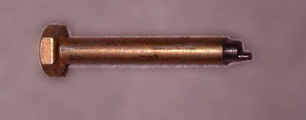
However, it shouldn't be that hard to do yourself. You'll need to make a little tool so you can move the adjustments in small increments; but that can be as simple as filing off part of a screwdriver tip. Here's a shot of the one I made as a simple lathe project:
The large round section fits into the 'window' in the gauge housing, while the smaller tip engages the slot. As you've probably noticed, the adjustment slot gets moved sideways, not turned.
Only other tools required are a source of constant 10 volts DC, a DMM, and some resistors to match the resistance of your sender at the two points you choose to calibrate at. (My suggestion would be 1/4 tank and 3/4 tank; but you could use empty and full if you want.) Measure the actual resistance of your sender at the two points (which may not be the same as new ones, especially if it is original to the car. They drift with time and wear.) Then stack up resistors to get close to the same reading. (Within 5% is plenty, this ain't rocket science.)
One of the adjustments affects the reading across the entire scale, the other mostly affects the reading near full. So, hook up the low side resistor (the one with more resistance), wait for the reading to settle (at least a minute, the movement is very slow) and move the low side adjustment to get the reading you want. Then hook up the high side resistor, wait for it to settle, and move the other adjustment. The adjustments do interact to some extent (especially if you use 1/4 and 3/4), so repeat the sequence a couple of times until you are happy with the results. Add a drop of clear nail polish to lock the adjustment, and a piece of tape to cover the slot, and you're done.

 Hey Guest!

 Hey - did you know if you click on the title of a thread it will take you to the first unread post since you last visited that thread?
 but were afraid to ask:
  STOP!! Never post your email address in open forums. Bots can "harvest" your email! If you must share your email use a Private Message or use the
  smilie in place of the real @
 Pretty Please - add it to our Events forum(s) and add to the calendar! >>