Hmm, I've never been very good at this part, but let's try a quick lesson in electricity:
Voltage is a potential, it doesn't really "flow". The usual comparison is water pressure. Imagine for a moment, a dam with water behind it, and a closed valve at the bottom. The pressure at the valve is kind of like voltage, it is just a potential for flow.
Current is kind of like the water flowing somewhere. So if you open the valve, you get some water flow. How much flow depends on how high the water is behind the dam (the voltage), plus how far you open the valve (which is comparable to resistance). If you measure the pressure before the valve, it will remain nearly the same, regardless of how much water is flowing. If you measure after the valve, you'll get nearly zero, again regardless of how much water is flowing.
After that, the comparison kind of breaks down, so we'll let it go at that. The important bit is that current and voltage measure different aspects of electricity.
The voltage stabilizer doesn't stabilize the voltage, what it stabilizes is the gauge reading. Since the gauge mechanism responds relatively slowly, the VS can work by switching between full battery voltage, and zero volts. (You didn't measure zero because your voltmeter doesn't respond quickly enough.) The VS is needed because the battery voltage is not a constant 12.0 volts but can rise to as much as 15 volts under some circumstances (like driving down the road on a cold day) and possibly drop below 12 volts (idling for a long time with the head lights, heater, and brake lights on).
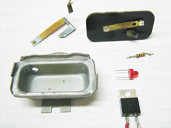
Inside, it has a coil of resistance wire, effectively an electric heater, wrapped around a bimetallic strip. The bimetallic strip consists of two different kinds of metal bonded together, with different rates of expansion with temperature. So when it gets hot, one side expands more than the other, and forces the strip into a curve. The end of the strip in the VS has a contact that closes when the strip cools, and applies ignition voltage to the heater (and to the gauges). The heater heats the strip up, the contacts open and the cycle repeats.
This sounds very complicated and Rube Goldberg, but for 1960 technology it is actually very simple, rugged, and most importantly, cheap. There are a surprising number of original voltage stabilizers that still work today! (Quite a contrast to my 1970 Audi, which used a crude electronic regulator that seemed to fail every 3 or 4 years.)
Inside the gauge is another heater and bimetal strip (on the left in your photos above). But this time, the end of the bimetal strip is connected to the indicator needle, through a linkage that magnifies the movement of the strip. How hot the heater gets depends on how much power it dissipates.
Since one side is supplied with (essentially) a constant 10 volts, the resistance of the sender is what controls the current through the gauge (and the voltage across it). Power is voltage times current, so the heater temperature (and hence needle position) depends on the resistance of the sending unit.
Clear as mud? There will be a quiz on Friday!


 Hey Guest!

 Hey - did you know if you click on the title of a thread it will take you to the first unread post since you last visited that thread?
 but were afraid to ask:
  STOP!! Never post your email address in open forums. Bots can "harvest" your email! If you must share your email use a Private Message or use the
  smilie in place of the real @
 Pretty Please - add it to our Events forum(s) and add to the calendar! >>