• Hi Guest!
    You can help ensure that British Car Forum (BCF) continues to provide a great place to engage in the British car hobby! If you find BCF a beneficial community, please consider supporting our efforts with a subscription.

    There are some perks with a member upgrade!
    **Upgrade Now**
    (PS: Subscribers don't see this gawd-aweful banner
Tips
Tips

Front wheel bearing - end float

RonR

Jedi Trainee
Country flag
Offline
I am in the process of replacing the front wheel bearings on a 1959 AH 3000.
I am retaining the distance piece and appropriate shims.

I have been told that there is an acceptable end float for the front wheel bearings, but I cannot find it in the BMC shop manual.

Does anyone where this information is documented, or what the allowable end float should be?

Thanks.
Ron
 
Zero with no binding when torqued to specification
 
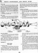
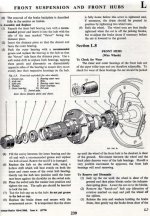
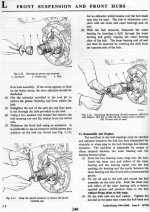
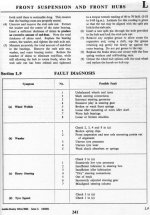
Hi Ron. Keoke is right, I have attached some pages out of the shop manual. You might find a bit of difference in the final set up depending on if you have enclosed ball bearings or tapered roller bearings. Section L.7 deals with ball bearings and L.8 deals with tapered roller bearings. the book doesn't give a spec as to degrees or inches of movement but talks about "Should you feel a very positive movement apparent then the bearings need to be renewed." When i do mine I set them up with the distance piece and the shims to give me "no" end play. You also want to make sure that you don't preload, meaning tightness, the bearings even when you torgue them to the specification range which is 40 to 70 lbs/ft. With the correct amount of shims and the distance piece you are tightening against the shims and the distance piece and not against the bearing rollers.
As for how loose do I allow them, well if I can feel the wheel rim move 1/8 inch that is too much to me. Ideally you should feel no play when you grab the wheel and move it in at the top and out at the bottom and visa versa. But as miles accrue you may get some movement but making them snug is the best bet. Here's some pics, I hope.
 

Attachments

  • img442.jpg
    img442.jpg
    75.8 KB · Views: 421
  • img443.jpg
    img443.jpg
    76.1 KB · Views: 500
  • img444.jpg
    img444.jpg
    72 KB · Views: 397
  • img445.jpg
    img445.jpg
    57 KB · Views: 334
Thanks all for the information.
I need to get the car back together this weekend, as I have been missing out on some above freezing driving days.
 
In actual fact you should make sure that there is some end float initially and keep and assemble dry as previously stated, then measure the end float with a dial gauge and adjust the shim pack accordingly, grease up and reassemble with the adjusted shim pack - it does take the guess work out of it.

:cheers:

Bob
 
how about tighten until you feel some bind then loosen nut I think it was 1 flat.
Jay '653000
 
That's not how they work. They need to be tight against the shims and distance piece with zero or barely detectable play.


Correct:
Because what you are actually doing is stiffening the axel by causing the distance piece to perform like a loaded column---that's Why--.:friendly_wink:
 
Just did this job on my 1960 BT7 resto.
did the left side before I read the posts here.
Wish I would have thought to do the adjustments dry
then grease the bearings lots easier that way.
The hardest part was setting up the dial indicator:highly_amused:
 
Correct:
Because what you are actually doing is stiffening the axel by causing the distance piece to perform like a loaded column---that's Why--.:friendly_wink:

Also too, the spacer on which the seal rides needs to be clamped down tight, lest it turn on the axle.
 
Also too, the spacer on which the seal rides needs to be clamped down tight, lest it turn on the axle.
Hi Bob
Could you clarify about the spacer the seal rides on?
the only spacers in my setup are the distance piece between the two bearing cones and the shims.
Want to make sure I didn't miss anything:rolleye:
 
Hi Bob
Could you clarify about the spacer the seal rides on?
the only spacers in my setup are the distance piece between the two bearing cones and the shims.
Want to make sure I didn't miss anything
:rolleye:
The spacer for the seal is only on the BJ8 spindles, the earlier axles have a seal surface integral to the stub axle (basically a
'step' just inboard of the inner bearing surface) but the BJ8 has a separate piece that slides on the axle before the bearing that provides a surface for the seal to run on.
Dave

Thanks for clarifying that. I guess I've been 'BJ8-centric' the last few years. I believe the BJ8 stub axles are considered more robust than earlier ones; maybe the separate spacer allows for a greater radius on the spindle base.
 
Bob, you are correct, the BJ8 spindles are much stronger and that's partially due to a much larger radius at the base of the axle.
Several years ago I broke a stock early type stub axle and now I run the DW 'uprated' early stub axles and they have
a very large radius and use the same seal surface piece the BJ8s use.
Dave
 
Thanks for the clarification good to know
The spacer for the seal is only on the BJ8 spindles, the earlier axles have a seal surface integral to the stub axle (basically a
'step' just inboard of the inner bearing surface) but the BJ8 has a separate piece that slides on the axle before the bearing that provides a surface for the seal to run on.
Dave
 
Correct:
Because what you are actually doing is stiffening the axel by causing the distance piece to perform like a loaded column---that's Why--.:friendly_wink:

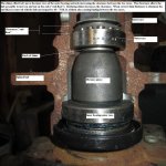
Sorry, but that is an incorrect statement, Keoke, if you're suggesting the distance piece helps strengthen the axle. That is an idea that comes up in every discussion of the distance piece. The distance piece's (plus shims) only function is to provide a way to get the proper pre-load on the bearings. It has nothing to do with strengthening the axle. The torque on the nut does not significantly increase the tensile stress on the axle. If it did load the axle significantly in tension, that would actually promote cracking of the axle on the bottom side at the hub because the tensile stresses in the radius at the base of the axle would be added to the upbending stresses there that the axle normally sees in operation.
 

Attachments

  • Wheel bearing adjustment.jpg
    Wheel bearing adjustment.jpg
    53.8 KB · Views: 582
Back
Top