• Hi Guest!
    You can help ensure that British Car Forum (BCF) continues to provide a great place to engage in the British car hobby! If you find BCF a beneficial community, please consider supporting our efforts with a subscription.

    There are some perks with a member upgrade!
    **Upgrade Now**
    (PS: Subscribers don't see this gawd-aweful banner
Tips
Tips

TR2/3/3A FRONT LIGHT WIRING ON TR3

habaneronut

Senior Member
Offline
Had the front wiring disconnected (don't ask why) and thought that I had all the connections numbered well so they could just be hooked right back up, but when I went to do so, all was not well. Parking and turn signals work correctly, but I have no headlights at all. I'm pretty sure the left side is O.K., but I have extra wires and receptacles on the right - I assume that could keep the left headlight from working as well as the right? Also, one of my tabs came off, so I am guessing where that wire goes. Here is what I have on the right.

Headlight: blue w/red and blue w/white as the book says, but then the black goes to a double connecter with two green w/brown wires from the harness(on the left side, the black goes to ground on the chassis). There is an extra connecter sleeve here from the harness that is green w/red.
I don't find one of them on the other side.

Parking: green w/white, red, and a black to ground on the chassis just as the manual says.

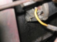
And, just to further complicate matters, coming out of the same sleeve that has a yellow going to the generator, is another wire with a ground connecter clip that is yellow w/green that is not connected to anything. I believe it should go to the generator also, but I can't figure out where and don't remember taking it loose.

And yes, everything worked well before I started disconnecting wires. Any ideas? I looked at the troubleshooting in the Lucas Fault book and that just completely confused me.

Fred
 
Hi Fred,
First thing you need to do is pull that black ground out out the green/brown (which is the horn circuit) connector. That's completing a hot side to a hot side connection. There should always be two black ground wires going to a spring metal double connector screwed down to the sheet metal just behind each horn. Those two grounds complete the circuits for your hi/low headlights and parking/turn indicator lights. It is a bit confusing with the seemingly extra green/red wires on the right with nothing plugging in and the extra green/brown on the left. Its just the way they manufactured the loom. The yellow/green wire is the field coil connection on the generator. The big solid yellow is the armature brush connection carrying all the produced current for the car. Most threes except possibly 3B's had screw on connectors. Some PO may have put in a later model generator with the push on, spade type connectors on yours. Just to back up, make sure you have four black grounds going to the sheet metal connectors on the fenders, two on each side.

Tom Lains
TS8651 & 58107
Yukon, OK
PS: You should look into joining our sister VTR club out of Tulsa - Green Country Triumphs.
 
If I'm reading the diagrams correctly, green w/brown should be a connection between the indicator switch to the flasher. Actually, a solid green wire comes from the direction indicator switch to a terminal at which it connects to the green w/brown wire from the flasher. Since pretty much anything with green as a main color is a power wire, it should NOT connect with a black ground wire.

The "extra connector sleeve...that is green w/red" would be for the LH direction indicator bulb filament. What you describe in "Parking: green w/white, red, and a black to ground on the chassis" is correct for the RH side only.

Hope that helps!
 
Oops, Andy's correct about the green brown wire. Even though I've owned these things for almost 40 yrs. one should always look at the diagram before opening one's mouth. It's still a hot side wire though.
Tom Lains
 
Thanks, Tom/Andy. I'll get back on this tomorrow armed with your advice and see if I can make good things happen. Guess I should have mentioned that although I have a 58 TR3A, the engine is an early 66 4A, so maybe that explains the different clips. So where exactly on the generator does the yellow/green clip on? Would that being unattached to anything explain why my ignition light never goes out? I just learned from another forum that that is not kosher, but it's been that way ever since I bought the car, even before any wires were disconnected. Man I've got a lot to learn about this LBC. Any and all advice very greatly appreciated.

I have joined Green Country Triumphs and exchanged a couple of emails. One of the members is going to go over the car with me if I ever get it to the point that I think I trust it to take me the 50 miles or so to where most of the members live. I'm kind of on the outskirts.

Fred
 
Nobody mentioned the spray contact cleaner that MUST be in your hand when you re-connect lucas connectors(AKA variable resistance inducers)
MD(mad dog)
 
Fred,

To answer your question from Aldwyns thread and given your recent wiring problem the generator might not be hooked up correctly or at all. I would compare all wiring against a wire diagram first and if all looks OK then ask what the next steps for checking the generator and regulator is in a new thread. Sorry, I just noticed you mentioed the Y/G wire is off. Before you reconnect your yellow/Green wire to the generator there should also be a yellow wire on the other post coming off the generator. You also need to know if your car is positive (or converted over to negative ground) so you can polarize the generator correctly. The red (charging indicator light)generator light is suppose to go out at a specified speed above low speed idle (no choke on). At idle the light may pulse slowly and dimly or barely come on. It's suppose to go out above idle speed. If it's a bright red light at any rpm it could mean the contacts are dirty in the control box (regulator) or it's not adjusted correctly. The generator may also have no output or is not polarized correctly. The battery could also be bad.

The following link will open a .PDF file with the correct wiring diagram. Scroll down until you see what best fits your cars description.

https://www.advanceautowire.com/tr24a.pdf
 
O.K. let's tackle the ignition light/generator wire first. The yellow wire to the generator is connected, and there is a spade connection just a couple of inches below it. Is that where the yellow/green wire goes? What effect does it have with the yellow/green disconnected? I have been driving the car, the battery checks out O.K., and I must be getting some charge back to it from the generator as only once has it been drained when I came out to start the car. The belt is tight. The gauge needle doesn't come far off center even at higher RPM and with no electricals on, though.

As to the lights, tackled them again with comments above in hand, and now I have all lights, but the left flasher doesn't work - it did yesterday when I had no headlights. Also, the right parking light and the left headlight are rather dim, and I'm almost certain that yesterday it was the left parking light that was not as bright. That's a ground problem, right? I checked all the grounds again, and they all seem O.K. to me. Maybe I better get some of the spray stuff and hit em with that though. I still have an empty socket green w/red on the right. There is just nothing left to go into it, but that's what you all said controls the left flasher, correct?

Making progress, I think!!

Fred
 
Yes, the yellow/green hooks up below the yellow but just as important is where it go's. With a continutity tester the yellow should go to the D terminal on the control box and the Y/G gos to the F terminal on the control box. If connected properly and the generator good, the ampmeter gauge should move to the + side and the red light should go out. if no change you will first have to test the generator for output. Generator test is as follows, connect both terminals of the generator together with a short wire, clip the negative lead of your voltmeter to one of the terminals on the generator, clip the positive lead to the body or a good ground. set the ide at 1000 rpm and the voltage should read 20 volts or better. DO NOT exceed the rpm or race the engine. Either it works or it doesn't. If that shows NG your either getting the generator rebuilt or buying a new one.
 
Can only add a micro bit more to what info you've gotten to this point. That's correct on the red/green wire/socket on the right side. It is, however, another opportunity for a poor connection and should be pulled apart and cleaned as per MadDog. In checking continuity/grounds etc. it sometimes is a help having a second person available to watch the results (eg. dimming/blinking when it's not supposed to) as you go from point to point moving and gently tugging wires/connectors. Speaking of which are generally bullet proof(oops), but having been pulled apart so many times in a lifetime, the wires start to break at the solder joints. It does pay to check them with a VOM and if you detect the slightest resistance, trim back and resolder. If the PO who installed the 4A engine did it right the spade connectors should be different sizes (yellow-big, yel/grn-small). If not (which may be why it comes loose) and they used crimp on connectors(common quick fix) change to a solder joint. Harry is right on about the generator, but if it doesn't charge, check the brushes and springs first. That's usually the cause(worked in a foreign car garage in my youth).
I'm just in the process of cleaning my block and will start actually putting mine back together after an embarrassingly lengthy hiatus(6 yrs). Hopefully maybe I'll see you and your 3 at a joint event next summer.

Tom Lains
 
O.K., lots more still to do then. With the holiday coming up, won't get to it until next weekend, so anyone who's interested in how this comes out watch for this topic to pop back to the top then.

Thanks for all the good advice. I've got all the books and studied them, but lots of times it just takes someone who's already been there to really explain what needs to be done.

Fred
 
Absolutely forgot about the brushes might needing replacement and something you can replace yourself.
Thanks Tom!
 
Got back to this way before I thought I would. Thanks to MadDog for the spray cleaner tip. I used this on my connections and roughed up the paint on the chassis at my grounds and now have nice bright headlights and parking lights. Trouble is, I still have no left flasher. The right flasher front and rear work fine, make a nice click, click, click sound at the flasher box when they are on. The left, however, makes one nice click, then kind of does a fast ick, ick ick with only the rear light flashing. Can't find anything in the manual that describes that kind of problem.

Still haven't connected up the yellow green to the generator. This is my first foray into auto mechanics, and I'm scared to death I'm going to fry something. Have tried to get a picture of this, hope it comes through below. I think the yellow green goes on the spade connection just to the left and under the yellow connection a bit, correct?

And now to confuse things even more, I was checking the wires at the voltage regulator box and noticed a single, solid blue wire coming into the solenoid through the firewall and the white/red wire that should be attached there just hanging free. I traced the blue back under the dash, and sure enough, it's wired into the starter where the white/red should be, and that unattached wire is just hanging there also. Why would a PO do something like that? Do the wires sometimes break inside the harness and have to just be rerouted like someone has done here?

Sorry to be such a pest, but I know you all have the right answers. I really appreciate all the help.

Fred
 

Attachments

  • 282842-misc11-21-06002.jpg
    282842-misc11-21-06002.jpg
    31.5 KB · Views: 188
[ QUOTE ]
The left, however, makes one nice click, then kind of does a fast ick, ick ick with only the rear light flashing. Can't find anything in the manual that describes that kind of problem.

Still haven't connected up the yellow green to the generator. This is my first foray into auto mechanics, and I'm scared to death I'm going to fry something. Have tried to get a picture of this, hope it comes through below. I think the yellow green goes on the spade connection just to the left and under the yellow connection a bit, correct?

And now to confuse things even more, I was checking the wires at the voltage regulator box and noticed a single, solid blue wire coming into the solenoid through the firewall and the white/red wire that should be attached there just hanging free. I traced the blue back under the dash, and sure enough, it's wired into the starter where the white/red should be, and that unattached wire is just hanging there also. Why would a PO do something like that? Do the wires sometimes break inside the harness and have to just be rerouted like someone has done here?

Sorry to be such a pest, but I know you all have the right answers. I really appreciate all the help.

Fred

[/ QUOTE ]

When the flasher goes ick ick ick it is as Andy says.

Re-read earlier post I made yes the Y/G go's to that post you are referring too but you should trace with continuity tester back to control box. (see earlier post) I'm not aware of wires just breaking in the harness but someone somewhere has probably had that happen. Usually wire problems are caused by PO's who take something apart and leave off long enough to forget where they all go back without marking or making notes. Did you get the wiring schematic? You need to study the diagram and check all your wiring before you put current to anything with a continuity tester.
 
Sorry, Harry, I did mean to put in the last post that I had checked that the yellow wire went to the D post on the control box, and the yellow green to the F as you cautioned and as per the wiring diagram (which I did have). That's when I noticed that single blue wire coming out of nowhere and attaching itself to the solenoid and I thought, "whoa, blue is supposed to be headlights, right?" I'm not much of a mechanic, at least not yet, but I sure didn't think that was right until I traced it and saw what had been done.

O.K., back to the connections with MadDog's spray in hand, and this time it's all gonna work!!

Fred
 
Hi Fred I will give my humble opinion. I remember when I went through some wiring on my 58 and was shocked to find those extra wires, the double green with a red/brown stripe. (Extra wires near to the same color and same place how bazaar.) I found it to be confusing because the wire for the turn light is green with a brownish red stripe. In fact, that little area you are in all the wires are either light green with brown stripes or green with red stripes that looks like they are brown. The extra wires I think are for those extra side fender mounted turn lights that might be required in some European countries or maybe fog lights (I am speculating) Anyways look at the colored stripe real close. When I get home I can take a better look if you need it. Yes make sure you get the grounds clean and tight, and if I remember right each small light socket has an addition grounding spot where it hooks to the body also. That additional blue wire going to the solenoid might just be where the PO tapped into the power. The solenoid is hot and often has some hot spade fittings sticking out to use for power. Everyone’s advice is excellent; and definitely check to see what grounding system you have, either negative or positive polarity. The generator light staying on bright and the car still charging is kinda confusing to me. I do know that if one side of the generator becomes unplugged the light will come on bright and stay on.
Good luck sp53
 
Back
Top