• Hey Guest!
    British Car Forum has been supporting enthusiasts for over 25 years by providing a great place to share our love for British cars. You can support our efforts by upgrading your membership for less than the dues of most car clubs. There are some perks with a member upgrade!

    **Upgrade Now**
    (PS: Upgraded members don't see this banner, nor will you see the Google ads that appear on the site.)
Tips
Tips

TR2/3/3A Exploded view or tr-3 signal switch needed

captainde

Member
Offline
Hello,

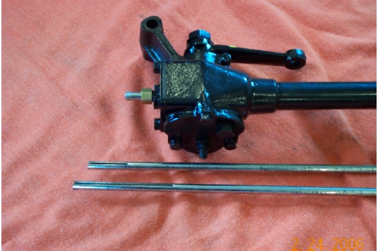
Does anyone have an exploded view of the signal switch mechanism on a 57 tr-3 with the adjustable steering wheel? Mine was put together incorrectly and the signal mechanism turns with the whole hub not allowing it to cancel out the signal lever.
Thanks,
captainde
 
Sorry, I don't have a good diagram. But the usual problem is either the stator tube is broken, or it's not locked securely at the front of the steering box. The stator tube runs through the center of the steering column and is not supposed to turn with the column. The back of the control head has a matching tube that slides over the end of the stator tube, with dimples that engage with a slot in the stator tube and thus keep the control head from turning.

For an adjustable wheel, the tube on the control head is much longer than for a fixed wheel. The slot in the stator tube is also longer, but I believe the tube itself is slightly shorter overall. So another problem might be if someone has mistakenly installed a non-adjustable control head into your adjustable wheel (and stator tube).
 
PS - here's what the TR2/3 Service Instruction Manual says "To fit control head and stator tube to the steering wheel" -

1. Place the steering wheel in the straight ahead position. This position can be checked by inspecting the alignment of all four wheels.

2. Feed the stator tube, with the anti-rattle springs in position, into the inner column of the steering unit with the tube slot uppermost and at the 12 o'clock position. Allow approximately 1 inch of tube to protrude from the end cover of the steering box.

3. Fit the brass olive to the protruding stator tube and secure with the gland nut. Loosen nut back one turn; this is retightened in a later operation.

4. Feed the wires from the short tube of the control head into and through the stator tube now in the steering unit. With the flasher control lever of the head at 12 o'clock ensure that the vertical lever of the stator tube plate is at the 6 o'clock position. Failure to observe this point will mean that the flashing indicators will not cancel correctly.

5. Secure the control head in the box of the steering wheel by tightening the three grub screws situated radially in the steering wheel hub. Do not move the steering wheel during this operation.

6. Tighten the gland nut to secure the stator tube to the steering box end cover and reconnect wires according to the colors or identification marks.

<whew>

Edit: manual later says "The control head on the adjustable steering unit is similar to the normal equipment with the exception of the stator tube. This consists of a short tube with indents at its lower end to form a key, and a longer tube with a slot at its upper end. The two tubes telescope together, the indents engaging with the slot provided. The purpose of this key and slot is twofold, firstly to prevent rotation with the steerig wheel and secondly to provide telescopic action as the steering wheel is adjusted on its splines.

* * * *

The procedure to fit control head is the same as fitting normal equipment, but it may be considered necessary to aply a smear of grease to the upper (slotted) end of the stator tube to ensure freedom of movement. It must be pointed out that over greasing at this point may lead to corrosion of the rubber insulation of the electrical harness and cause short circuiting. The electrical harness protruding from the stator tube must be free to allow a portion to be drawn into the tube when the steering wheel is adjusted to a higher position."
 
Thanks Randall and Obi Wan,

I will look at it more closely and see if I can find out if the stator tube is correct.
Captainde
 
Captain,

You are not alone!
Thanks for asking this question, your timing is perfect for problems I'm addressing on my TR3.

When I turn the steering wheel my horn will sometimes blow and one of the turn signal lights just started coming on at its own discression. I'm afraid my wires in the stator tube are wrapped up like a hemp rope causing many of my issues.

Good luck, let us know how things "turn" out!
 
Royal_58 said:
I'm afraid my wires in the stator tube are wrapped up like a hemp rope
Almost guaranteed, if your head turns with the wheel.

BTW, AFAIK Mark Macy is the only current source of new stator tubes:
https://macysgarage.com/myweb6/Parts/other_tr2_3_parts.htm#TR2/3%20Stator%20Tube
He's also provided a nice photo of the difference in the slot between the fixed and adjustable versions
StatorTube.jpg
 
The dirty little secret on the new control heads is that they come with the wire ends soldered inplace.It is nearly impossible to put them through the tube with the ends on,and a snap with them removed.Save your self a lot of bad language and wasted drinking time,remove them first......
MD(mad dog)
 
I can't seem to open the PDF file for this,
can someone help me
I would really like to use this bit of information as i am having trouble in this area right now.
 
Related question: After removing the grub/set screws and detaching the wires out of the steering box, is it possible to pull out the control head the length of the exposed wires without loosening the nut and olive? Or do the nut and olive "clamp" or compress the four wires where you cannot pull the control head? I want to replace just the horn push and front face.
 
Yes, you can pull it with the olive tight...BUT!

You must either straighten the wires completely where they enter the olive, or even better, have someone feed them in while you pull at the top.

AND...this is quite the necro-post. I didn't even have a TR when this was first posted!
 
Never let a dormant thread go to waste! Thanks, John.
 
Here is a link for a control head manual or tech article. https://www.tr-register.co.uk/forums/index.php?app=core&module=attach&section=attach&attach_id=6013
Hopefully, it works.
Berry

I am having the same sort of issue, but this link from the UK says it is not available here (Canada) and the original link has a mysterious message about a database error visible only to who???? not me.
My tube is plugged with oversize wires and I have new wiring "harness" from Moss. The connectors are staggered.

There is another article somewhere about dealing with the head itself and I cannot find it. I shall have to open the head to connect the new wiring, I think. Does anyone know it?

BTW which way does the horn spring fit?. Parts diagram shows its large end down/forward, but the descriptions seem to describe it with the small end fitting into the column?( down/forward.)

Michael
 
There is an article here on disassembly of the control head...

https://www.tr-register.com.au/Files/technical.htm

You might need to scroll down to see it on the site.

If that still doesn't work for you Dr. Mike, email me and I will send you the word files via email.

cheftush AT Hotmail.com (remember to replace the AT with an @)

Cheers
Tush
Thank you, Tush. I found it and down loaded it and it should answer all my questions. now to get v[back to work..
Michael
 
No wonder there is no follow-up article on reassembling the control head: but it is done. It took a few hours of trial and error, and saved me the $200 odd that a new head would have cost. It would have been easy except that one of the small contact screws came adrift and fell into the works which meant I had to take the whole darned thing apart. The only thing missing was a lock washer on the brown terminal, for which I should have a spare somewhere, and the button to locate the narrow end of the horn spring, which I may replace with silicone goop. Or something.

The dining room table can now be restored to normal use!
 
I had to take mine apart a dozen times...on my lap, since I didn’t want to pull out the wires. It turned out to be a poorly cast plastic part in the end, so no fiddling was going to fix it. I had to buy a new one anyway. I’m fast at taking them apart now!?!
 
THanks: it takes a lot of perseverance. I don't think I made it to 12 but it was close! All the screws are now in, as of five minutes ago!. Not much progress in the simmer as the garden takes over. Etc. Waiting for painter, who I think is on holiday. He has all the loose parts but needs to finish the body. Must put stabilizer in the gas too.

It never ends, does it!

Michael
 
Back
Top