• Hi Guest!
    You can help ensure that British Car Forum (BCF) continues to provide a great place to engage in the British car hobby! If you find BCF a beneficial community, please consider supporting our efforts with a subscription.

    There are some perks with a member upgrade!
    **Upgrade Now**
    (PS: Subscribers don't see this gawd-aweful banner
Tips
Tips

Electrical Help Please

65_BRG_Sprite

Jedi Warrior
Country flag
Offline
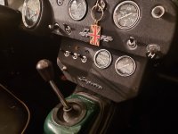
I have rebuilt a later year radio console to house 2 gauges and 4 switches. 2 of the switches are for driving lamps and fog lamps. Each is wired in with solenoids. The lamps work well. Now I want to connect a small, colored bezel lamp above each switch to indicate if they have accidently switched on. Would someone please draw a simple diagram as how to do this? I will attempt a photo shortly.
 
Wiring diagram needed for bezel lamps.
 

Attachments

  • Sprite Console.jpeg
    Sprite Console.jpeg
    1 MB · Views: 125
I preseume you want the electrical diagram and not the where to put the lightbulb diagram - which is up to you. :D

This should work

1640962379002.png
 
JP: my ignorance is apparent. I guess I should have said relay instead of solenoid. My additional driving and fog lamps are connected to 4-pin relays. Tomorrow or Sunday I will run down how I have them connected. Your sketch has me befuddled. If I understand your sketch correctly, all I have to do is install the indicator light in the power line to the relay?
 
JP: my ignorance is apparent. I guess I should have said relay instead of solenoid. My additional driving and fog lamps are connected to 4-pin relays. Tomorrow or Sunday I will run down how I have them connected. Your sketch has me befuddled. If I understand your sketch correctly, all I have to do is install the indicator light in the power line to the relay?
Pretty much all you have to do - BUT you must install it in parallel and not series. The temptation would be to take the indicator, cut the power line to the relay - and attach the indicator light inbetween. This will however reduce the power to the relay itself.

If you splice the indicator light to that wire but ground it to the car (as per the digram) then, when there is power to the relay but also power to the light.

The difference between parallel and series (to get it in your head) is that with parallel any one light can burn out and the rest stay lit - with series, one burned out bulb takes out the whole string (like Christmas lights :rolleyes2:

Your relay should be wired as per the diagram - the power from the battery goes through the switch on the dash then to terminal #87 on the relay. It comes out #85 and goes to ground. (or vice versa - it is a switch so the order doesn;t really matter)

Turning on the switch engages the 'heavier' part of the relay - power will come into #30 and out #87 to the headlights and then to ground.

They have relay diagrams here as well if it helps

 
A friend of mine asked a similar question a couple of weeks back. He wanted a logic diagram showing how I would set up a simple relay system for head, driving, and fog lamps. Here is my sketch. Perhaps it will help on your project?
 

Attachments

  • headlight fog and driving relays.pdf
    137.9 KB · Views: 145
Big thanks to JP and Bill! And you also Basil for running this forum. Your directions are exactly what was needed. Excited, heating the garage up this afternoon to have some fun.
At 70 I'm never too old to learn- but If I forget and ask again in a day or two I hope you'll forgive. Cheers!
 
Big thanks to JP and Bill! And you also Basil for running this forum. Your directions are exactly what was needed. Excited, heating the garage up this afternoon to have some fun.
At 70 I'm never too old to learn- but If I forget and ask again in a day or two I hope you'll forgive. Cheers!
ask what? :ROFLMAO: seriously - keep us posted and don't forget to disconnect the battery first - don't ask me how I know.
 
Back
Top