
-
 Hey Guest!
British Car Forum has been supporting enthusiasts for over 25 years by providing a great place to share our love for British cars. You can support our efforts by upgrading your membership for less than the dues of most car clubs. There are some perks with a member upgrade!**Upgrade Now**
(PS: Upgraded members don't see this banner, nor will you see the Google ads that appear on the site.)
-
 When posting a classified ad, you MUST select a prefix from the drop-down next to the subject line. If you don't you will get an error and your ad will not be posted!

Tips
- We have a special forum called "Member Articles" where you can submit actual articles for consideration for publication. Learn More
- Don't have an Avatar? If not, your avatar will default to the 1st character in your username. Go into "Account Details" to change your Avatar.
- Some basic forum navigation info: click
 Hey - did you know if you click on the title of a thread it will take you to the first unread post since you last visited that thread?
- Hey Guest - Is your British Car Club in our Clubs database? If not, send me a PM - Basil

- Looking for a local club? Click the "Clubs" tab above and browse hundreds of clubs world-wide.
- Add Android or iPhone APP: click
- Did you know - any picture or video you add in your posts in any marque-specific forum will also get added to the Media Gallery automatically.
- A few more tips about posting and replying: click
- Hey there Guest - be sure to keep your profile page up to date with interesting info about yourself: learn more
- More tips and tricks on Posting and Replying: click
 but were afraid to ask:
  STOP!! Never post your email address in open forums. Bots can "harvest" your email! If you must share your email use a Private Message or use the
  smilie in place of the real @
- Want to mention another member in a post & get their attention? WATCH THIS

- So, you created a "Group" here at BCF and would like to invite other members to join? Watch this!
- Hey Guest - A post a day keeps Basil from visiting you in the small hours and putting a bat up your nightdress!
- Hey Guest - do you know of an upcoming British car event?
 Pretty Please - add it to our Events forum(s) and add to the calendar! >> Here's How <<
- Hey Guest - you be stylin' Change the look and feel of the forum to fit your taste. Check it out
- If you run across an inappropriate post, for example a post that breaks our rules or looks like it might be spam, you can report the post to the moderators: Learn More
- If you would like to try some different "looks" or styles for the site, scroll to the very bottom, on the left and click the Style Selector.
You are using an out of date browser. It may not display this or other websites correctly.
You should upgrade or use an alternative browser.
You should upgrade or use an alternative browser.
Wedge Don - any news on the TR7/8?
- Thread starter tdskip
- Start date

Offline
And the question was...?
DNK
Great Pumpkin
Offline
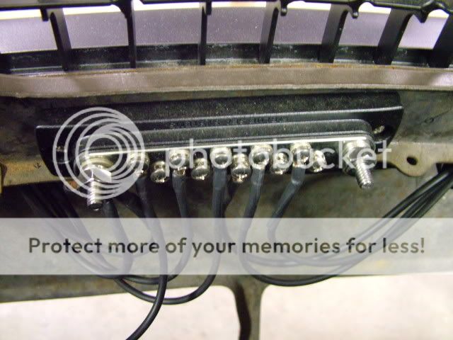
I am going to install 2 innovate O2 sensors with gauges,also bought an Innovate oil pressure gauge and they all need grounds and the O2 controls say NOT to use Battery ground so I was going to install a ground bar like I have all over the 6 :
 .
.
Want to know where a good spot to tie that to the body inside or out. Is the computer grounded too? Can I tie that in too.
I also need key power for it. Is there usually a free connection on the ign. switch?
Want to know where a good spot to tie that to the body inside or out. Is the computer grounded too? Can I tie that in too.
I also need key power for it. Is there usually a free connection on the ign. switch?
White wires are switched power. There is a bundle of them that share the power from the ignition switch located behind the fuse panel up high. There is also a bundle of grounds up there that tie into the body above the footwell fresh air vent doo. I installed similar bars with switched power and constant power in the engine bay behind the right hand headlight mounts. Makes installation of electric gizmos real easy. No more searching for wires to draw power from wondering if they can support the additional load.
There should be a sticker on the back side of your fuse cover that shows what each fuse is and their ratings. Not all of the covers I've seen have the sticker. If yours doesn't, I can dig one with a sticker out and snap a photo of it. The wiring diagram shows what is connected to each fuse. You just have to do a little detective work to figure it out. Don't run anything directly from the white wires. The whites are switched power that is to be run to a relay to act as a trigger. All of the white wires get their power directly from the ignition switch after it ties into the bundle I mentioned above. The white wire circuit isn't rated to have much current passing thru it. The white wires should have power whenever the key is in the on position. Any white wire with a secondary trace color is switched power going to a specific electrical device.(usually on the downstream side of a relay) That is why they are usually thicker wire. Those are designed to have a current draw on them. Hope this helps. Four years of electrical engineering school and I understand this so well I became a plumber.
Just run a white wire from the bundle to the bar. Then any time you need a switched power, just take it from the bar. Install a second bar that gets constant power all the time. Take that lead from the terminal on the main cable where it runs up from the floor to the fuse box. There should be a bare terminal under the black plastic cover. If what you are installing requires a decent amount of current, install it using a relay that gets power from the two bars. In line fuses are also nice to have. You can just ground to the body. You can use the bars to get power for the electric fans, fuel pump, radio, ignition box, electric water pump, etc.
You can tap into any white wire if that is easier, but I like the bundle connection. Disconnect the battery. Remove the screws that hold the fuse panel to the back of the glove box. Pull the box down and you will have access to all of the wiring from below. Not the easiest task. Sort of like removing the clutch master from the firewall.
DNK
Great Pumpkin
Offline
Will tackle the electrical afte it's started.
Well, have all the shafts in and locked down with the bolts cutting across the shafts in the appropriate spot.
Headers are on with, I think, the rad next.
Oops, got to fix the location of the #1 cyl. on the dizzy by spinning the pump some how.
Dang,always something.
Well, have all the shafts in and locked down with the bolts cutting across the shafts in the appropriate spot.
Headers are on with, I think, the rad next.
Oops, got to fix the location of the #1 cyl. on the dizzy by spinning the pump some how.
Dang,always something.