• Hi Guest!
    You can help ensure that British Car Forum (BCF) continues to provide a great place to engage in the British car hobby! If you find BCF a beneficial community, please consider supporting our efforts with a subscription.

    There are some perks with a member upgrade!
    **Upgrade Now**
    (PS: Subscribers don't see this gawd-aweful banner
Tips
Tips

Degree the cam....name those tools game.

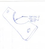
Okay. Kinda like a hair cut. So I gave it a shave;
just a little trim around the edges, huh?

Thanks for the idea, Doc.

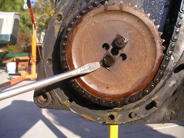
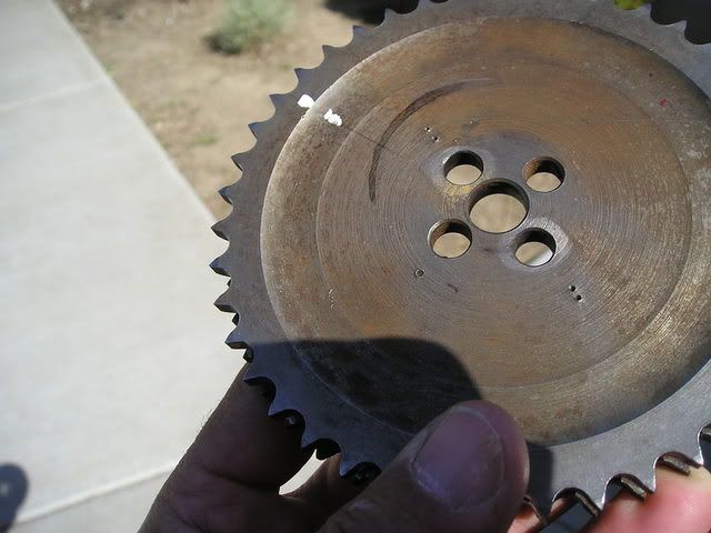
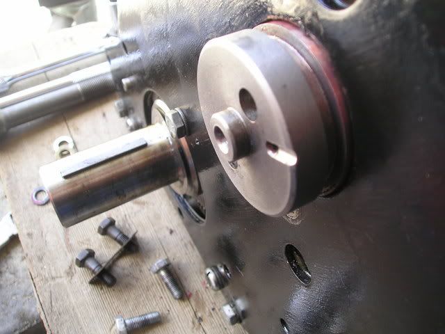
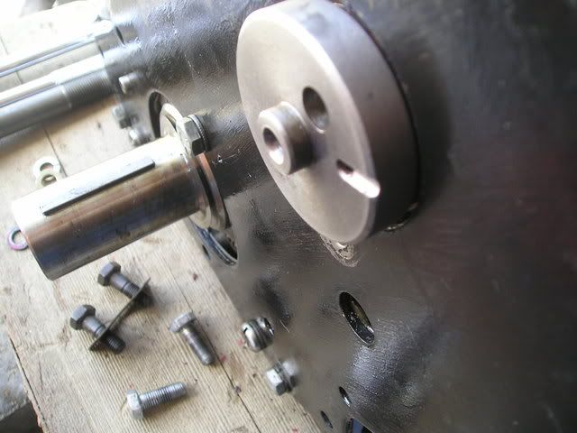
Another thought. I have been looking for shim or
shim-type material to place behind the retainer,
between the retainer and the block.

Reason? The groove in the cam flushes so closely
with the face of the block. Was trying to create,
say, .004 tolerance or so there. Makes me think to
try a coat or two (or three?) of paint on the back
side of the retainer.

So if a small amount of paint were to chip off, do
you see a problem? We are talking chain, here, in
speedy rotation. Shouldn't be a problem if it were to
happen, do you think?
 
Also, sorry, I didn't measure the thing before I
started. I'm hoping that others will learn from
what I'm doing, so I should have done this; but my
ignorance has me not mearsuring such finite detail.

I am sure there is a tool for this. Anybody want
to explain what it is and maybe how to use it?

Sorry, folks. U stuck with me now.
 
As an aside, I meant to refer another member to an old
thread, for reference.

Sent him the thread name and the date. So can somebody
tell me how to refer someone to another thread?

Thanks.
 
2wrench,

To see exactly where the bind is, might try some machinist's blue(dykem), put a little on the inside collar of the holding plate and install, remove and inspect to see where the contact is.

As for the shim material, any competent, established parts house/machine shop can get you some old shim stock, it is still available. And then there's the alternative of finding an old feeler blade set, cutting and drilling the blade you want to use as a spacer.
 
I don't see any reason to shim the retainer, Dennis. It *should* keep the groove of the cam flush with the block face.
Ron's Machinist's blue suggestion would be definitive as to what's bound,. He posted THAT before, too. The stuff is handy as a shop supply for just such problems.

Not recalling *exactly* what the retainer looks like, pardon the crudity of the illustration, but: shaving the radiused part along it's I.D. is what I'm suggesting. This is also the place to apply the Dykem to see if it leaves "witness" transfer of the dye on the cam.
 

Attachments

  • 10797.jpg
    10797.jpg
    54.6 KB · Views: 179
2wrench said:
Also, sorry, I didn't measure the thing before I
started. I'm hoping that others will learn from
what I'm doing, so I should have done this; but my
ignorance has me not mearsuring such finite detail.

I am sure there is a tool for this. Anybody want
to explain what it is and maybe how to use it?

Sorry, folks. U stuck with me now.

"Micrometers"... 0'~1.0" range. :wink:


WE're stuck with YOU?!?!


I think it's t'other way 'round. :smirk:
 
Very nice drawing, Doc, and a huge thanks.

Check this pic of my work in progress:

P1010001-28.jpg


This shown, it just doesn't seem to matter what I do,
this thing will torque to about 10lbs and that's it.
It's almost as if this is what it's supposed to be.
I actually got out my vibrating-style electric sander
to lap down the width some more. Now I'm working down
the inside diameter as well as the thinckness.

Do you suppose, say, 9 pounds torque and some Locktite
Red will do the job?

I mean, yes, it's on the engine, but the retainer itself
doesn't move.

I will get it, sooner or later, I know. So let's look
past for just a moment. I will now post a photo of my
cam gear before removal:

P1010023-1.jpg


This picture shows two marks plus a scribed line. That's
it. I want to identify what was there originally, versus
what my son tapped onto it.

I've been told in degreeing the cam, that I am to ignore
all markings and use the protractor/dial gauge approact
atop the valve lifter. What confuses me is I then
heard something about....."Then you line up the dots the
best you can without disturbing the orientation of crank
gear to cam gear; turning it now to make sure she turns
360 and back to where it began," or something to that
effect.

So, are these original marks used, ultimately?

Also, for note: I did find, clearly, a mark on the end
of my old cam. Was told this is somehow helpful.

Still in the soup.........
 
Opps, meant to show one more pic:

P1010001-29.jpg


This pic shows four dots in a line. I think my
son put those on. By this pic's orientation,
there are dots at about 8:00 o'clock and roughly
10:00 o'clock with a scribed line...also some
white to designate that marking.

These I have just described are the original marks,
I believe.
 
<div class="ubbcode-block"><div class="ubbcode-header">Quote:]Also, sorry, I didn't measure the thing before I
started.[/QUOTE]

Dennis,

Regarding the thickness. Do you remember these? Where are you at now as far as the thickness goes?
 
Paul: Thought it would be expensive. I'll make a visit
to the parts store and see what they have. Be
checking for Dykem as well.
Be posting results.
 
Please post a picture of the cam plug in the back of the block.
 
Paul: Right now the back plate is still on the engine,
so that plug is covered. We considered that as a possible
problem some time back. No problem to revisit it once
again, though.

So without pulling off the rear engine plate, I took a
couple pictures showing the cam both pulled out of the
block slightly (well showing the machine groove that the
cam retainer fits into).

Then I have another photo showing that the cam is well
pushed into the block of the engine and that the machined
groove is pushed so deep into the block that it is no
longer visible (which I think means that there is nothing
obstructing the cam from entering the block to appropriate
depth).

If there is another reason you seek a peek at that plug,
let me know. I do need to remove that rear engine plate
anyway in order to put in a new bushing in the flywheel.

Now the pictures. First with cam pulled out:

P1010002-29.jpg


Now with the cam pushed in:

P1010001-30.jpg
 
Also, Paul, I purchased a micrometer.

At one end of the retainer (near the bolt hole) it
measures .180.

At the other end of the retainer (near the bolt hole)
it measures .182.

So there is .002 difference between the two.
 
TR3driver said:
2wrench said:
And maybe some poor soul from a local club
would help me. I just don't know. Club members, you
reading this?????
Why not contact Triumph Travelers directly ?

I'll bet if you showed up for the meeting tomorrow and promised to help with TRfest, you'd get someone to help with your engine
grin.gif

https://www.triumphtravelers.org/Activites/act08/activityList2008.php

Curious, Randall. Were you there? Were you the "someone" who would help me
with my engine?

Actually, I seriously considered it; but I kept messing with it today, instead.
I'm not really any closer, cept I bought a micrometer and took some
measurements.
 
Dennis,

In my humble opinion, I think that it should be flat across the plane. But from the pictures that you show, the came seems to be far enough back in the block, so I don't think that the 0.002" would matter, with the total float allowance in the specs.

But looking at the pictures a bit more, when facing the cam, is it an optical illusion or is the right side of the cam gap smaller on the right than on the left? And if so, why?

With the plate mounted that could be an artificial twist of sorts and could cause your binding.
 
If the cam pushes back that far, clearly the issue is not the cam binding against something else. So torquing down the retainer is causing the retainer to bind in the slot, either by forcing it farther into the slot (binding against the bottom) or by twisting it in either of two axes (binding against the sides). I'll third the suggestion of machinist's blue as being the easiest way to find the problem (I keep a rattle can of it on the bench all the time); but I think you could probably learn something by trying to run a thin feeler gauge in between the retainer and the slot. First with no bolts at all (where you should find the prescribed clearance or maybe a bit more), then with the bolts snugged up. If you can find where the clearance goes down, that will tell you which way the retainer is being twisted. If you can still measure clearance with the cam bound up, then it has to be the retainer hitting the bottom of the slot.

I live somewhat south of Los Angeles; or I'd run up and give you a hand myself (whether or not you offered to help with TRfest
grin.gif
) But I know from experience that finding enough volunteers to cover all the jobs is a popular topic at planning meetings, and such an offer would give you an excuse for attending the planning meeting today ... showing up just to ask for help probably wouldn't have been as well received.

Besides I'm leaving for a family vacation with my new wife tomorrow, and I really need to finish getting ready ... :jester:

PS, just checked, Tracy to my home is farther than Chicago to St. Louis
 
That 0.002" difference is incidental, IMO. The possibility of the front plate being somehow "cocked" didn't enter my thoughts, but IS it? Looks like a perspective or POV illusion.

The plate should be flush to the block with the gasket as the only thing betwixt.
 
Hi,have you had the cam bearings changed and line bored?Try putting the retainer in the cam slot and then pushing the cam and retainer firmly against the block face and look to see that the retainer sits flush against the block face and flush against the outer part of the cam slot.as you have already relieved the thickness and the internal radius of the retainer it might be a problem of the squareness of the cam to block face or the cam slot has been machined slightly angled to the center line of the cam.you definitely have to find out the cause as you could get to the point of reducing the retainer to a point that it will not bind but the cause is something else.
 
just another thought on checking the alignment of the cam groove and the cam-push the cam all the way in and put a straight edge across the face of the cam to accentuate any misalignment and measure the distance between the straight edge and the block face at the furthest point possible,repeat measurement at 90 degrees .repeat the process holding the straight edge against the face of the cam groove. if you have bought calipers as per the previoous foto you could use them as a straight edge,
 
Oh, my! I am not putting a gasket behind the retainer.
Is there supposed to be one there? If there is, I
missed this one. Could this be the problem?

Oh, wait, Doc. You are speaking of the front engine
plate. Sorry. Yes, the front engine plate with the
gasket. That's it. I did place a thin layer of gasket
sealant and torqued to specs (don't remember the number)
from the Bently Manual.
 
Back
Top